The circulating water system in industrial production consumes a lot of fresh water during operation. At the same time, in order to prevent scaling of industrial equipment, various chemical agents need to be continuously added to the circulating water, and sewage needs to be continuously discharged and fresh water needs to be added. This not only causes a great waste of water resources but also pollutes the environment. In view of this, the author designed an industrial circulating water polarization control system based on ARM. The system realizes the treatment function of industrial circulating water through the polarization effect of the polarization field on water [1], thereby achieving the purpose of reducing water resource consumption, avoiding the use of chemical agents, and effectively preventing water resource pollution.
1 System overall design plan
The industrial circulating water polarization control system based on ARM uses ST's STM32F103 microcontroller as the main control core. The polarization energy detection circuit detects the circulating water quality parameters in real time. After the STM32F103 operation processing, the polarization energy output circuit adjusts the output of polarization energy. The LCD display circuit displays the operating parameters and setting parameters in real time. The switch input circuit controls the input of the signal, and the operating data is stored in the extended RAM. The system structure is shown in Figure 1.
Figure 1 Structure of industrial circulating water polarization control system based on ARM
2 System hardware design

2.1 Main Controller
The industrial circulating water polarization control system based on ARM uses the 32-bit enhanced flash microcontroller STM32F103 based on the Cortex-M3 core as the control core, which has the characteristics of high performance, low power consumption, and good real-time performance [2]. The operating frequency of STM32F103 can reach 72 MHz, with 512 KB of flash memory and 64 KB of SRAM, 12-bit successive approximation ADC, which can be converted in single, continuous, scanning or intermittent mode; the channel sampling time is programmable, the total conversion time can be reduced to 1 μs, and supports DMA data transmission [3].
The STM32F103 can use the timer-triggered synchronous injection mode to achieve synchronous sampling of multiple analog signals; it has three USART serial communication interfaces and a built-in baud rate generator, with a programmable baud rate of up to 4.5 Mbit/s for both sending and receiving; the flexible static memory controller FSMC can be connected to the 16-bit PC card interface through synchronous or asynchronous memory, making it easy to expand external memory and LCD display.
2.2 Polarization energy output circuit
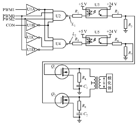
The polarization energy output circuit synthesizes, isolates and amplifies the PWM polarization energy control signal output by the STM32F103 through hardware logic, and then outputs it to drive the polarizer, generating a polarization electric field to act on the circulating water. As shown in Figure 2, the polarization energy output circuit consists of PWM output logic control, photoelectric isolation, output drive, energy boost and output.
The PWM output logic control is composed of NOT gates U1A~U1D and NAND gates U2 and U4. The PWM has three signals: PWM0, PWM1, and PWM2, and a CON output control signal. The cycles of the three PWM output signals are exactly the same. The duty cycles of PWM0 and PWM1 are adjusted according to the actual operation needs of the polarization energy. PWM2 is a PWM signal with a duty cycle of 50%. Together with PWM0 and PWM1, it controls the N-MOS power tubes Q1 and Q2 to conduct in the range of 0 to 180° and 180° to 360° in one cycle, respectively, to ensure that Q1 and Q2 are not output at the same time, effectively avoiding output short circuit.
Figure 2 Polarization energy output circuit

The waveforms of PWM0, PWM1, PWM2, L1 position point, L2 position point, and polarization output u are shown in Figure 3.
Figure 3 The waveforms of PWM0, PWM1, PWM2, L1 position point, L2 position point, and polarization output u

In order to improve the system working stability and anti-interference ability, and realize the conversion of output level, U3 and U5 optocouplers are designed to realize the isolated transmission of output PWM signal. R2 and R3, R6 and R7 respectively form a voltage divider circuit to realize the driving function of Q1 and Q2. R4, C1, R8 and C2 form a resistance-capacitance absorption protection circuit to absorb the instantaneous high voltage pulse generated by the primary coil of the step-up transformer [4], thereby protecting Q1 and Q2.
2.3 Polarization energy detection circuit
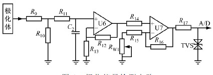
The polarization energy detection circuit consists of a sampling circuit, an active filter circuit, a signal amplification and a limiting protection circuit, as shown in Figure 4. R9 and R10 constitute the sampling circuit. R9 and R10 select precision, low-temperature drift wirewound resistors to ensure stable and reliable signal acquisition when the system works in a wide temperature environment. R11, C2, and U6 form a first-order low-pass active filter circuit. The cutoff frequency of the filter is designed to be 45 Hz, which can effectively filter out the 50 Hz industrial frequency interference signal on site. The limiting protection circuit uses an electrostatic discharge protection component TVS to effectively prevent the high-voltage pulses or signals generated by the start and stop of large motors and other equipment on industrial sites from exceeding the limit and affecting the subsequent circuits.
Figure 4 Polarization energy detection circuit

2.4 LCD display circuit
The LCD display circuit uses a dedicated segment LCD screen, and the display content includes parameters such as the set polarization value, polarization energy operation value, and authorized operation time. The LCD display is completed by a liquid crystal driver chip HT1622. HT1622 is a 32×8 LCD driver with a built-in RC oscillator, providing 1/4 bias and 1/8 COM cycle [5]. It is connected to STM32F103 through a serial data line, read, write and chip select control signals. At the same time, the upper computer or touch screen HMI displays water quality parameters and other working parameters in real time through the RS485 communication interface.
3 System software design
The ARM-based polarization control system software was developed in the KeiluVision 4 environment [5] for industrial circulating water, using C language programming and modular design. The main program modules include initialization module, polarization energy data acquisition module, timing data acquisition and PID function operation module, LCD display driver module, and protection function module.
The main functions of the main program are to complete I/O pin configuration, timer working mode and constant configuration, serial port working mode and startup control, PWM working mode, interrupt source initialization and system parameter setting; the LCD display driver module realizes parameter data conversion and display functions, including driver chip initialization, display bit separation, display font code conversion, and writing to the display image area.
Since the polarization energy output of this system acts on the industrial circulating water system, its output effect is reflected as a large inertia lag system. Therefore
, the polarization energy output control adopts the digital PID regulation control method. The specific program flow is shown in Figure 5.
Figure 5 Polarization energy output control subroutine flow
4 Conclusion

Two industrial circulating water polarization control systems based on ARM were applied in the circulating water system of a power plant (defined as equipment A and equipment
B respectively), and the addition of chemical agents to the circulating water system was stopped. The system has been in operation for more than one year, and its anti-scaling, descaling, sterilization and algae removal effects are ideal. The operating data of some full-time points on September 6, 2011 are shown in Table 1.
It can be seen from Table 1 that the system can control the circulating water to operate at a higher concentration ratio (4.50-5.20), so the discharge of sewage can be reduced; since the circulating water system no longer adds chemicals for treatment, the pollution of the discharged water to rivers, etc. is also avoided. The actual operation effect of the system shows that it meets the on-site operation requirements of circulating water in thermal power plants.

Previous article:Design of railway signal intelligent lighting system based on power line carrier
Next article:Design and application of embedded WEB server in solar power station monitoring system
- Popular Resources
- Popular amplifiers
 Professor at Beihang University, dedicated to promoting microcontrollers and embedded systems for over 20 years.
- LED chemical incompatibility test to see which chemicals LEDs can be used with
- Application of ARM9 hardware coprocessor on WinCE embedded motherboard
- What are the key points for selecting rotor flowmeter?
- LM317 high power charger circuit
- A brief analysis of Embest's application and development of embedded medical devices
- Single-phase RC protection circuit
- stm32 PVD programmable voltage monitor
- Introduction and measurement of edge trigger and level trigger of 51 single chip microcomputer
- Improved design of Linux system software shell protection technology
- What to do if the ABB robot protection device stops
- Keysight Technologies Helps Samsung Electronics Successfully Validate FiRa® 2.0 Safe Distance Measurement Test Case
- Innovation is not limited to Meizhi, Welling will appear at the 2024 China Home Appliance Technology Conference
- Innovation is not limited to Meizhi, Welling will appear at the 2024 China Home Appliance Technology Conference
- Huawei's Strategic Department Director Gai Gang: The cumulative installed base of open source Euler operating system exceeds 10 million sets
- Download from the Internet--ARM Getting Started Notes
- Learn ARM development(22)
- Learn ARM development(21)
- Learn ARM development(20)
- Learn ARM development(19)
- Learn ARM development(14)
- Application of electromagnetic functional composite materials in radar antenna covers
- Noise Countermeasures Using Capacitors
- I have a few questions about the WM8978 audio amplifier board.
- Guess what development board this is?
- ST programmable sensor + FSM on Unico
- Digital Circuits and Digital Systems: Experiments and Course Design Training Course
- AT91SAM7S256 serial port data loss
- Using DSP motor speed measurement and detailed explanation
- Low-power Qorvo chips enhance connectivity and reliability for new Luna smart home system
- Highlights of Bluetooth Mesh Technology

 HMC390LP4E


 京公网安备 11010802033920号