Main components:
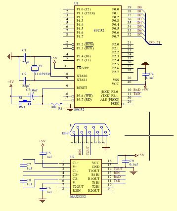
1. AT89C52 single-chip microcomputer chip, used to control serial port communication.
2. Interface level conversion chip MAX3232 is used to realize the conversion between TTL level and RS-232 level.
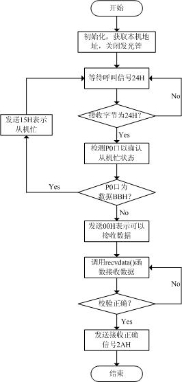
Test flow chart: host part

Slave part:

Test circuit diagram:

Test program code:
//PPDataR.h program
#ifndef _PPDATAR_H // Prevent PPDataT.h from being referenced repeatedly
#define _PPDATAR_H
#include
#include
#define uchar unsigned char
#define uint unsigned int
/* Handshake signal macro definition */
#define CALL 0x24 // Host call
#define BUSY 0x15 // Slave is busy
#define OK 0x00 // Slave is ready
#define SUCC 0x2A // Receive successfully
#define ERR 0xF0 // Receive error
#define MAXLEN 64 // Maximum length of the buffer
uchar buf[MAXLEN];
#endif
//PPDataR.c program
#include "PPDataR.h"
/* Send data function */
uchar recvdata(uchar *buf)
{
uchar i,tmp;
uchar len; // Save data length
uchar ecc; // Save the check byte
/* Receive data length bytes */
RI = 0;
while(!RI);
len = SBUF;
RI = 0;
/* Use the value of len to initialize the check byte ecc */
ecc = len;
/* Receive data */
for (i=0;i { while(!RI); *buf = SBUF; ecc = ecc^(*buf); // Perform byte check RI = 0; buf++; } *buf = 0; // indicates the end of data /* Receive checksum byte */ while(!RI); tmp = SBUF; RI = 0; /* Perform data verification */ ecc = tmp^ecc; if (ecc!=0) // If the check is wrong { *(buf-len) = 0; // Clear the data buffer /* Send verification error signal ERR */ TI = 0; SBUF = ERR; while(!TI); TI = 0; return 0xff; // Return 0xff to indicate verification error } /* Send verification success signal SUCC */ TI = 0; SBUF = SUCC; while(!TI); TI = 0; return 0; // Verification successful, return 0 } void init_serial() { TMOD = 0x20; // Timer T1 uses working mode 2 TH1 = 250; TL1 = 250; TR1 = 1; // Start timing PCON = 0x80; // SMOD = 1 SCON = 0x50; // Working mode 1, baud rate 9600kbit/s, receiving is allowed } /* Main program */ void main() { uchar tmp = 0; /* Serial port initialization */ init_serial(); EA = 0; // Disable all interrupts while(1) { /* If the received data is not CALL, continue waiting */ while (tmp!=CALL) { RI = 0; while(!RI) tmp = SBUF; RI = 0; } /* Check the P0 port to determine whether it is currently busy. If P0=0xBB, it is busy */ P0 = 0xff; tmp = P0; if(tmp==0xBB) // If the P0 port is 0xBB, send a BUSY signal { TI = 0; SBUF = BUSY; while(!TI); TI = 0; continue; } /* Otherwise, send an OK signal, indicating that the slave can receive data */ TI = 0; SBUF = OK; while(!TI); TI = 0; /* Data receiving */ tmp = 0xff; while(tmp==0xff) { tmp = recvdata(buf); // If verification fails, 0xff is returned; if reception succeeds, 0 is returned } } }
Previous article:Single chip microcomputer realizes short distance wireless transmission
Next article:Realizing Intelligent Signal Generator Using Integrated Chip MAX038
- Popular Resources
- Popular amplifiers
- Learn ARM development(16)
- Learn ARM development(17)
- Learn ARM development(18)
- Embedded system debugging simulation tool
- A small question that has been bothering me recently has finally been solved~~
- Learn ARM development (1)
- Learn ARM development (2)
- Learn ARM development (4)
- Learn ARM development (6)
 Professor at Beihang University, dedicated to promoting microcontrollers and embedded systems for over 20 years.
- LED chemical incompatibility test to see which chemicals LEDs can be used with
- Application of ARM9 hardware coprocessor on WinCE embedded motherboard
- What are the key points for selecting rotor flowmeter?
- LM317 high power charger circuit
- A brief analysis of Embest's application and development of embedded medical devices
- Single-phase RC protection circuit
- stm32 PVD programmable voltage monitor
- Introduction and measurement of edge trigger and level trigger of 51 single chip microcomputer
- Improved design of Linux system software shell protection technology
- What to do if the ABB robot protection device stops
- Analysis of the application of several common contact parts in high-voltage connectors of new energy vehicles
- Wiring harness durability test and contact voltage drop test method
- From probes to power supplies, Tektronix is leading the way in comprehensive innovation in power electronics testing
- From probes to power supplies, Tektronix is leading the way in comprehensive innovation in power electronics testing
- Sn-doped CuO nanostructure-based ethanol gas sensor for real-time drunk driving detection in vehicles
- Design considerations for automotive battery wiring harness
- Do you know all the various motors commonly used in automotive electronics?
- What are the functions of the Internet of Vehicles? What are the uses and benefits of the Internet of Vehicles?
- Power Inverter - A critical safety system for electric vehicles
- Analysis of the information security mechanism of AUTOSAR, the automotive embedded software framework
- Qorvo launches payload products into space to commemorate its 5th anniversary, speaking with strength!
- Temperature measurement in the electronics and semiconductor industries
- Working principle and structure analysis of variable frequency series resonance
- EEWORLD University ---- Linux driver strategy and framework
- Phase shifter classification and working principle (Part 1)
- [TI recommended course] #Live replay: Application of TI millimeter wave sensors in smart home#
- EEWORLD University ---- Live playback: The most important component of the analog world - Signal chain and power supply: Amplifier special
- Help, how to calculate the voltage gain of an amplifier circuit?
- Xilinx XPE Power Estimation Software Setup Advisory
- Electronic password lock based on single chip microcomputer

 LM7121IN


 京公网安备 11010802033920号