With the widespread application of embedded systems, various small terminals need to develop USB interfaces to connect with the outside world. At present, there are two commonly used technologies. The USB interface based on single-chip microcomputers is characterized by the need for external chips, complex circuits, and few CPU resources left; the USB interface based on ARM is characterized by rich resources, but there are many ARM series products. If the selection is not appropriate, more peripheral circuits need to be connected, and the CPU performance cannot be well exerted.
USB (Universal Serial Bus) is the abbreviation of universal serial bus. It has become the mainstream interface of computers because of its convenience, dynamic bandwidth allocation, excellent fault tolerance and high cost performance.
This design uses Samsung's ARM9 core S3C2440A chip as the CPU, because the chip integrates all the components for controlling USB, and the peripheral circuit is simple and easy to implement.
1 Features of S3C2440A
The CPU part of S3C2440A mainly integrates power module, reset and clock module, touch screen and keypad module, program memory and data memory module. At the same time, it provides the following rich peripheral interfaces: synchronous memory (SDRAM) and NAND FLASH control interface, which can be expanded to 1 GB of storage space; 4 DMA channels and 24 interrupt ports; can control STN LCD and TFT LCD display, support touch screen function; USB interface type A and type B each; 3 serial ports, I2C, SPI, I2S and other interfaces; with AC97 audio interface; with SD card, digital camera interface and network interface.
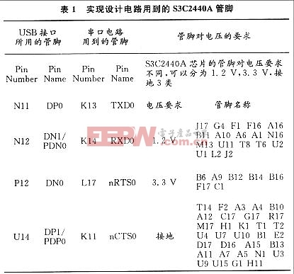
S3C2440A also has multiple working modes, the pins are distributed in a 17×17 square shape, numbered from left 1 to right 17 horizontally, and numbered from bottom A to top U vertically, classified as A1~A17, B1~B17, C1~C17 and so on to U1~U17. The functions corresponding to these pins are not unique. Usually, as long as the enable changes, S3C2440A can achieve different control functions. The pins of S3C2440A involved in this design are divided into 3 categories as shown in Table 1.
2.2 Serial port
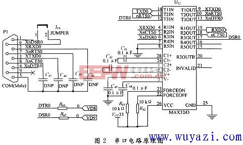
circuit The role of the serial port in this design is to load the USB driver through the computer, and the principle is shown in Figure 2.
2.3 Power supply circuit
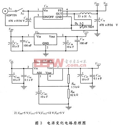
Since the pins of the S3C2440A chip have different requirements for voltage, it is necessary to complete the power supply transformation, and its principle is shown in Figure 3.
3 Research on driver
According to the USB interface, its device structure can be divided into USB Host (host) and USB Device (external device). The USB host controls the USB device to communicate, while the host and the host, or the USB device and the USB device cannot communicate.
3.1 USB host
The functions of the USB host usually include the following parts: verify whether the USB device is inserted or removed; control the data flow between the USB host and the device; return the displayed status of the USB host. The
USB system software consists of the following three parts: host controller driver (HCD), USB driver (USBD), and host software (Host Software). The functions of the host controller are shown in Table 2. HCD and USBD contain software interfaces based on different abstraction levels. The two work together in a certain way to complete tasks to realize the functions of the USB system. There is no specific definition of the difference in their tasks, but one of the functions that HCD must have is that it must support a variety of different host controller chips. In some operating systems, when the system must implement certain basic functions, it can be implemented by the host software.

3.2 USB transfer types
USB defines four types of transfers: control transfer, synchronous transfer, interrupt transfer, and batch transfer. Among them, control transfer refers to reliable, non-periodic, bursty communication initiated by the host client software, mainly used for the transmission of control commands and status information; synchronous transfer refers to periodic and continuous communication between the host and the device, generally used to transmit real-time information. This type retains the ability to include the concept of time in the data, but the transmission is not necessarily urgent; interrupt transfer refers to the transmission of a small amount of data, low speed, and periodic; batch transfer refers to non-periodic, large, and reliable transmission, and its typical application is to transmit data that can utilize bandwidth.
3.3 USB device request
USB devices should respond to request commands from the host through the default control pipe (Default Control Pipe). These requests are completed by using control transfers. The request and the request parameters are sent to the device through the Setup packet, and the host is responsible for setting the value of each field in the Setup packet. There are three types of requests included in USB device requests: standard, manufacturer, and device class. Standard requests are used to complete the device enumeration process; manufacturer requests are used to complete user-defined requests; device class requests refer to requests transmitted by certain specific USB device classes, such as printer classes. Device request requirements have strict definitions, including type, device request, value, index, and length.
3.4 USB driver structure
The S3C2440A chip supports USB1.1 protocol and USB 2.0 protocol. This design is for USB Host (host, type A) and is written based on USB 1.1 protocol. The program structure and data transmission flow are shown in Figure 4.
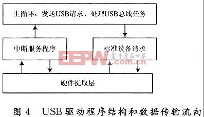
The writing of the driver is mainly divided into the following parts: hardware abstraction layer, interrupt service program, standard device request and main loop. The hardware abstraction layer implements the direct read and write operations of S3C2440A on the I/O port; the interrupt service program handles various interrupts, including requests on the bus task; the standard device request completes various standard requests sent by the host, which is used to complete various enumeration requests; and the main loop is responsible for completing the data collection and other tasks of the foreground. After all tasks are completed, they must return to the main loop.
4 Conclusion
This design uses Samsung's ARM9 S3C2440A chip as the CPU. Compared with the original single-chip microcomputer-based model, the peripheral circuit is simpler and it is easy to reliably implement the USB interface function of the embedded terminal. In debugging, the embedded development board GEC2440A kit used also provides a serial port tool DNW. This tool can be used to detect whether the driver is correct or not. For example, if the program is written correctly, the DNW serial port will prompt "USB IS CONNECT". Since the S3C2440A chip has rich functions, such as the processor can improve the computing speed, the LCD can interact with the human-computer, and the network port can connect to the Internet, the developed embedded terminal can not only improve the overall performance, but also lay the foundation for future applications.
Keywords:ARM
Reference address:Embedded USB interface design based on ARM
USB (Universal Serial Bus) is the abbreviation of universal serial bus. It has become the mainstream interface of computers because of its convenience, dynamic bandwidth allocation, excellent fault tolerance and high cost performance.
This design uses Samsung's ARM9 core S3C2440A chip as the CPU, because the chip integrates all the components for controlling USB, and the peripheral circuit is simple and easy to implement.
1 Features of S3C2440A
The CPU part of S3C2440A mainly integrates power module, reset and clock module, touch screen and keypad module, program memory and data memory module. At the same time, it provides the following rich peripheral interfaces: synchronous memory (SDRAM) and NAND FLASH control interface, which can be expanded to 1 GB of storage space; 4 DMA channels and 24 interrupt ports; can control STN LCD and TFT LCD display, support touch screen function; USB interface type A and type B each; 3 serial ports, I2C, SPI, I2S and other interfaces; with AC97 audio interface; with SD card, digital camera interface and network interface.

S3C2440A also has multiple working modes, the pins are distributed in a 17×17 square shape, numbered from left 1 to right 17 horizontally, and numbered from bottom A to top U vertically, classified as A1~A17, B1~B17, C1~C17 and so on to U1~U17. The functions corresponding to these pins are not unique. Usually, as long as the enable changes, S3C2440A can achieve different control functions. The pins of S3C2440A involved in this design are divided into 3 categories as shown in Table 1.

2.2 Serial port
circuit The role of the serial port in this design is to load the USB driver through the computer, and the principle is shown in Figure 2.

2.3 Power supply circuit
Since the pins of the S3C2440A chip have different requirements for voltage, it is necessary to complete the power supply transformation, and its principle is shown in Figure 3.

3 Research on driver
According to the USB interface, its device structure can be divided into USB Host (host) and USB Device (external device). The USB host controls the USB device to communicate, while the host and the host, or the USB device and the USB device cannot communicate.
3.1 USB host
The functions of the USB host usually include the following parts: verify whether the USB device is inserted or removed; control the data flow between the USB host and the device; return the displayed status of the USB host. The
USB system software consists of the following three parts: host controller driver (HCD), USB driver (USBD), and host software (Host Software). The functions of the host controller are shown in Table 2. HCD and USBD contain software interfaces based on different abstraction levels. The two work together in a certain way to complete tasks to realize the functions of the USB system. There is no specific definition of the difference in their tasks, but one of the functions that HCD must have is that it must support a variety of different host controller chips. In some operating systems, when the system must implement certain basic functions, it can be implemented by the host software.

3.2 USB transfer types
USB defines four types of transfers: control transfer, synchronous transfer, interrupt transfer, and batch transfer. Among them, control transfer refers to reliable, non-periodic, bursty communication initiated by the host client software, mainly used for the transmission of control commands and status information; synchronous transfer refers to periodic and continuous communication between the host and the device, generally used to transmit real-time information. This type retains the ability to include the concept of time in the data, but the transmission is not necessarily urgent; interrupt transfer refers to the transmission of a small amount of data, low speed, and periodic; batch transfer refers to non-periodic, large, and reliable transmission, and its typical application is to transmit data that can utilize bandwidth.
3.3 USB device request
USB devices should respond to request commands from the host through the default control pipe (Default Control Pipe). These requests are completed by using control transfers. The request and the request parameters are sent to the device through the Setup packet, and the host is responsible for setting the value of each field in the Setup packet. There are three types of requests included in USB device requests: standard, manufacturer, and device class. Standard requests are used to complete the device enumeration process; manufacturer requests are used to complete user-defined requests; device class requests refer to requests transmitted by certain specific USB device classes, such as printer classes. Device request requirements have strict definitions, including type, device request, value, index, and length.
3.4 USB driver structure
The S3C2440A chip supports USB1.1 protocol and USB 2.0 protocol. This design is for USB Host (host, type A) and is written based on USB 1.1 protocol. The program structure and data transmission flow are shown in Figure 4.

The writing of the driver is mainly divided into the following parts: hardware abstraction layer, interrupt service program, standard device request and main loop. The hardware abstraction layer implements the direct read and write operations of S3C2440A on the I/O port; the interrupt service program handles various interrupts, including requests on the bus task; the standard device request completes various standard requests sent by the host, which is used to complete various enumeration requests; and the main loop is responsible for completing the data collection and other tasks of the foreground. After all tasks are completed, they must return to the main loop.
4 Conclusion
This design uses Samsung's ARM9 S3C2440A chip as the CPU. Compared with the original single-chip microcomputer-based model, the peripheral circuit is simpler and it is easy to reliably implement the USB interface function of the embedded terminal. In debugging, the embedded development board GEC2440A kit used also provides a serial port tool DNW. This tool can be used to detect whether the driver is correct or not. For example, if the program is written correctly, the DNW serial port will prompt "USB IS CONNECT". Since the S3C2440A chip has rich functions, such as the processor can improve the computing speed, the LCD can interact with the human-computer, and the network port can connect to the Internet, the developed embedded terminal can not only improve the overall performance, but also lay the foundation for future applications.
Previous article:Detailed explanation of uboot transplantation
Next article:Hardware Design of Embedded USB Host
- Popular Resources
- Popular amplifiers
Recommended Content
Latest Microcontroller Articles
He Limin Column
Microcontroller and Embedded Systems Bible
 Professor at Beihang University, dedicated to promoting microcontrollers and embedded systems for over 20 years.
MoreSelected Circuit Diagrams
MorePopular Articles
- LED chemical incompatibility test to see which chemicals LEDs can be used with
- Application of ARM9 hardware coprocessor on WinCE embedded motherboard
- What are the key points for selecting rotor flowmeter?
- LM317 high power charger circuit
- A brief analysis of Embest's application and development of embedded medical devices
- Single-phase RC protection circuit
- stm32 PVD programmable voltage monitor
- Introduction and measurement of edge trigger and level trigger of 51 single chip microcomputer
- Improved design of Linux system software shell protection technology
- What to do if the ABB robot protection device stops
MoreDaily News
- Allegro MicroSystems Introduces Advanced Magnetic and Inductive Position Sensing Solutions at Electronica 2024
- Car key in the left hand, liveness detection radar in the right hand, UWB is imperative for cars!
- After a decade of rapid development, domestic CIS has entered the market
- Aegis Dagger Battery + Thor EM-i Super Hybrid, Geely New Energy has thrown out two "king bombs"
- A brief discussion on functional safety - fault, error, and failure
- In the smart car 2.0 cycle, these core industry chains are facing major opportunities!
- The United States and Japan are developing new batteries. CATL faces challenges? How should China's new energy battery industry respond?
- Murata launches high-precision 6-axis inertial sensor for automobiles
- Ford patents pre-charge alarm to help save costs and respond to emergencies
- New real-time microcontroller system from Texas Instruments enables smarter processing in automotive and industrial applications
Guess you like
- How to choose the appropriate main circuit topology for power supply?
- The diameter of the four holes on the EK140 base plate
- This circuit is called a "lawn mower"
- CC3200-LAUNCHXL
- In a single-chip computer, writing 1 clears it to 0, and writing 0 clears it to 0. What is the difference?
- How to monitor battery voltage with Arduino
- Image Algorithm Transplantation to DSP and Its Optimization Steps
- To advance in technology to a certain level, you just need to read more datasheets!
- 51 STM32 reference study manuals, one-click download without points!
- With the advent of 5G, what should we pay attention to when designing mobile phone antennas?

 INA141P


 京公网安备 11010802033920号