Buzzers are mainly divided into two types: piezoelectric buzzers and electromagnetic buzzers.
The electromagnetic buzzer consists of an oscillator, an electromagnetic coil, a magnet, a vibrating diaphragm and a shell. After the power is turned on, the audio signal current generated by the oscillator passes through the electromagnetic coil, causing the electromagnetic coil to generate a magnetic field. Under the interaction of the electromagnetic coil and the magnet, the vibrating diaphragm vibrates periodically and makes a sound.
The piezoelectric buzzer is mainly composed of a multivibrator, a piezoelectric buzzer, an impedance matcher, a resonance box, a shell, etc. The multivibrator is composed of a transistor or an integrated circuit. When the power is turned on (1.5~15V DC working voltage), the multivibrator starts to vibrate and outputs an audio signal of 1.5~2.5kHZ. The impedance matcher drives the piezoelectric buzzer to sound.
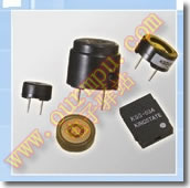
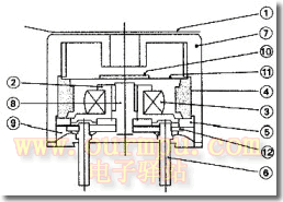
Below is the appearance picture and structure diagram of the electromagnetic buzzer

Electromagnetic buzzer physical picture: Electromagnetic buzzer structure diagram: \'

Internal structure of electromagnetic buzzer:
1. Waterproof sticker
2. Spool
3. Coil
4. Magnet
5. Base
6. Pin
7. Shell
8. Core
9. Sealing glue
10. Small iron sheet
11. Vibrating membrane
12. Circuit board [page]
1. Driving principle of electromagnetic buzzer
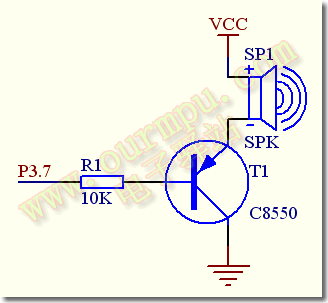
The principle of buzzer sound is that the current passes through the electromagnetic coil, which makes the electromagnetic coil generate a magnetic field to drive the vibration membrane to make sound. Therefore, a certain current is required to drive it. The current output by the IO pin of the microcontroller is small, and the TTL level output by the microcontroller basically cannot drive the buzzer. Therefore, a current amplification circuit is needed. The S51 enhanced microcontroller experiment board uses a transistor C8550 to amplify and drive the buzzer. The schematic diagram is shown in Figure 3 below:

S51 enhanced single chip microcomputer experiment board buzzer driver schematic diagram:
The positive pole of the buzzer is connected to the VCC (+5V) power supply, and the negative pole of the buzzer is connected to the emitter E of the transistor. The base B of the transistor is controlled by the P3.7 pin of the microcontroller after passing through the current limiting resistor R1. When P3.7 outputs a high level, the transistor T1 is cut off, no current flows through the coil, and the buzzer does not sound; when P3.7 outputs a low level, the transistor is turned on, so that the current of the buzzer forms a loop and sounds. Therefore, we can control the level of the P3.7 pin through the program to make the buzzer sound and turn it off.
By changing the frequency of the waveform output by the P3.7 pin of the microcontroller in the program, the tone of the buzzer can be adjusted to produce sounds of various timbres and tones. In addition, by changing the duty cycle of the high and low levels of the P3.7 output level, the volume of the buzzer can be controlled. We can verify these through programming experiments.
2. Buzzer Example
Below we give a few simple examples of programming and circuit design of microcontroller-driven buzzers.
1. Simple buzzer experiment program: This program drives the buzzer on the experimental board to emit a buzzing sound by outputting a square wave in the audio range at P3.7. The function of the DELAY delay subroutine is to make the output square wave frequency below 20KHZ within the hearing capacity of the human ear. Without this delay program, the output frequency will greatly exceed the hearing capacity of the human ear, and we will not be able to hear the sound. Changing the delay constant can change the output frequency, and thus adjust the tone of the buzzer. You can change #228 to other values in the experiment and listen to the change in the tone of the buzzer.
ORG 0000H
AJMP MAIN ; Jump to the main program
ORG 0030H
MAIN: CPL P3.7 ;Buzzer drive level inversion
LCALL DELAY ;Delay
AJMP MAIN ;Repeated loop
DELAY:MOV R7,#228 ; Delay subroutine, changing the delay constant can change the tone of the buzzer
DE1: DJNZ R7,DE1
RET
END
2. Reversing warning sound experiment procedure: We know that various trucks and container trucks will emit a reversing warning buzzer sound when reversing, and the warning yellow light will also flash synchronously to remind the people or vehicles behind to pay attention. This experimental routine realizes the reversing warning function, and the warning sound is emitted by the buzzer on the experimental board, and the yellow warning light is emitted by the two yellow LEDs on P1.2 and P1.5 on the experimental board. [page]
ORG 0000H
AJMP START ; Jump to initialization program
ORG 0033H
START:
MOV SP,#60H ;SP initialization
MOV P3,#0FFH ;Port initialization
MAIN: ACALL SOUND; buzzer sound
ACALL YS500M; delay
AJMP MAIN
SOUND:
MOV P1,#11011011B ;Light up 2 yellow warning LEDs
MOV R2,#200 ;Sound for 200 cycles
SND1: CLR P3.7 ;Output low level T1 conducts, buzzer sounds
ACALL YS1ms ;Delay
SETB P3.7 ;Output high level T1 cuts off, buzzer does not sound
ACALL YS1ms ;Delay
DJNZ R2,SND1
MOV P1,#0FFH ;Turn off the yellow warning light
RET
YS1ms: ;1ms delay subroutine
MOV R0,#2
YL1: MOV R1,#250 ;Changing the value of R0 can change the sound frequency
DJNZ R1,$
DJNZ R0,YL1
RET
YS500M: ;500ms delay subroutine
MOV R0,#6
YL2: MOV R1,#200
YL3: MOV R2,#250
DJNZ R2,$
DJNZ R1,YL3
DJNZ R0,YL2
RET
END
3. "Ding Dong" electronic doorbell experimental program: When a guest visits, if you press the doorbell button of a common household electronic doorbell, a "ding dong" sound will be emitted indoors. This experimental program simulates the pronunciation of the electronic doorbell. When we press the K1 button on the experimental board, the buzzer emits a "ding dong" music sound. It is a more practical program.
"Ding Dong" electronic doorbell experiment ASM source program: "Ding Dong" electronic doorbell C language source program:
ORG 0000H
LJMP START; jump to the initialization program
ORG 000BH
LJMP PGT0 ; Jump to T0 interrupt service routine
START:
OBUF1 EQU 30H ; Initialize program
OBUF2 EQU 31H
OBUF3 EQU 32H
OBUF4 EQU 33H
FLAGB BIT 00H
STOPB BIT 01H
K1 BIT P3.2 ; Define button K1 as doorbell button
MOV TMOD,#02H ; Initialize timer
MOV TH0,#06H
MOV TL0,#06H
SETB ET0 ; Start timer T0
SETB EA ; Start general interrupt
MAIN: ;Main program
JB K1,MAIN ;Test K1 button
LCALL YS10M ;Delay de-jitter
JB K1,MAIN
SETB TR0 ;Button is valid
MOV P1,#00H ;Light up the button indicator
MOV OBUF1,#00H
MOV OBUF2,#00H
MOV OBUF3,#00H
MOV OBUF4,#00H
CLR FLAGB
CLR STOPB
JNB STOPB,$
MOV P1,#0FFH
LJMP MAIN ;After sending out the "ding dong" sound, return to re-test the button
YS10M: ;10ms delay subroutine
MOV R6,#20
D1: MOV R7,#248
DJNZ R7,$
DJNZ R6,D1
RET
PGT0: ;Timer T0 interrupt service program
INC OBUF3 ;A "ding-dong" sound is emitted in the interrupt service program
MOV A,OBUF3
CJNE A,#100,NEXT
MOV OBUF3,#00H
INC OBUF4
MOV A,OBUF4
CJNE A,#20,NEXT
MOV OBUF4,#00H
JB FLAGB,PGSTP
CPL FLAGB
AJMP NEXT
PGSTP:
SETB STOPB
CLR TR0
LJMP INT0RET
NEXT: JB FLAGB,SOU2
INC OBUF2
MOV A,OBUF2
CJNE A,#03H,INT0RET
MOV OBUF2,#00H
CPL P3.7
LJMP INT0RET
SOU2: INC OBUF1
MOV A,OBUF1
CJNE A,#04H,INT0RET
MOV OBUF1,#00H
CPL P3.7
LJMP INT0RET
INT0RET:
RETI [page]
END
#include
unsigned char obuf1;
unsigned char obuf2;
unsigned int obuf3;
bit stopb;
bit flagb;
void main(void)
{
unsigned char i,j;
TMOD=0x02; //Timer T0 initialization
TH0=0x06;
TL0=0x06;
ET0=1;
EA=1; //Enable general interrupt
while(1)
{
if(P3_2==0) //Detect K1 button
{
P1=0x00;
for(i=10;i>0;i--)
for(j=248;j>0;j--);
if(P3_2==0)
{
obuf1=0;
obuf2=0;
obuf3=0;
flagb=0;
stopb=0;
TR0=1; //Start timer T0 and make a "ding-dong" soundwhile
(stopb==0);
P1=0xff;
}
}
}
}
void t0(void) interrupt 1 using 0
{
obuf3++;
if(obuf3==2000)
{
obuf3=0;
if(flagb==0)
{
flagb=~flagb;
}
else
{
stopb=1;
TR0=0;
}
}
if(flagb==0)
{
obuf2++;
if(obuf2==3)
{
obuf2=0;
P3_7=~P3_7;
}
}
else
{
obuf1++;
if(obuf1==4)
{
obuf1=0;
P3_7=~P3_7;
}
}
}
Previous article:Design a digital voltmeter using AT89S51 microcontroller and ADC0809
Next article:51 single chip microcomputer 8*8 dot matrix LED display principle and program
Recommended ReadingLatest update time:2024-11-16 15:54


- Popular Resources
- Popular amplifiers
-
 西门子S7-12001500 PLC SCL语言编程从入门到精通 (北岛李工)
 -
 Principles and Applications of Single Chip Microcomputers and C51 Programming (3rd Edition) (Xie Weicheng, Yang Jiaguo)
 -
 Teach you to learn 51 single chip microcomputer-C language version (Second Edition) (Song Xuefeng)
 -
 Hand-drawn illustrations revealing the secrets of communication circuits and sensor circuits (Mims III)
 Professor at Beihang University, dedicated to promoting microcontrollers and embedded systems for over 20 years.
- Innolux's intelligent steer-by-wire solution makes cars smarter and safer
- 8051 MCU - Parity Check
- How to efficiently balance the sensitivity of tactile sensing interfaces
- What should I do if the servo motor shakes? What causes the servo motor to shake quickly?
- 【Brushless Motor】Analysis of three-phase BLDC motor and sharing of two popular development boards
- Midea Industrial Technology's subsidiaries Clou Electronics and Hekang New Energy jointly appeared at the Munich Battery Energy Storage Exhibition and Solar Energy Exhibition
- Guoxin Sichen | Application of ferroelectric memory PB85RS2MC in power battery management, with a capacity of 2M
- Analysis of common faults of frequency converter
- In a head-on competition with Qualcomm, what kind of cockpit products has Intel come up with?
- Dalian Rongke's all-vanadium liquid flow battery energy storage equipment industrialization project has entered the sprint stage before production
- Allegro MicroSystems Introduces Advanced Magnetic and Inductive Position Sensing Solutions at Electronica 2024
- Car key in the left hand, liveness detection radar in the right hand, UWB is imperative for cars!
- After a decade of rapid development, domestic CIS has entered the market
- Aegis Dagger Battery + Thor EM-i Super Hybrid, Geely New Energy has thrown out two "king bombs"
- A brief discussion on functional safety - fault, error, and failure
- In the smart car 2.0 cycle, these core industry chains are facing major opportunities!
- The United States and Japan are developing new batteries. CATL faces challenges? How should China's new energy battery industry respond?
- Murata launches high-precision 6-axis inertial sensor for automobiles
- Ford patents pre-charge alarm to help save costs and respond to emergencies
- New real-time microcontroller system from Texas Instruments enables smarter processing in automotive and industrial applications
- Why embedded engineers have misunderstandings about 8-bit MCUs
- ST official statement: STM8 and STM32 production capacity description
- Practical Tips
- Are Gallium Arsenide (GaAs) technology solid-state power amplifiers important? Let's discuss its development trend.
- NUCLEO_G431RB review——by bigbat
- Sell Tektronix oscilloscope tds3052B tds3054B tds3064B
- Unboxing ESP32-S2-Kaluga && Laser PM2.5 Sensor
- SD NAND and STM32 series successful experience sharing
- BK3432 BK3431Q Bluetooth ble chip Bluetooth smart lock application
- When the wifi module is not soldered, it will keep printing errors

 西门子S7-12001500 PLC SCL语言编程从入门到精通 (北岛李工)


 京公网安备 11010802033920号