Abstract: A control method with local feedback is proposed to improve the traditional active power filter control method. This method has the advantages of being able to completely eliminate system oscillations and reduce the distortion rate of grid-side current and common connection point voltage. Simulation analysis results verify the effectiveness of this method.
Keywords: active power filter; resonance; control method; high-pass filter
1 Introduction
Active power filter (APF) is a new type of device that dynamically suppresses harmonic current and compensates reactive power. It has the advantages of fast response speed, good compensation effect, and can realize dynamic continuous real-time compensation. Its basic principle is to inject a compensation current equal to the harmonic current and reactive current and opposite in direction into the power grid, so as to eliminate harmonics, make the grid-side current sinusoidal and the power factor of the grid 1. Therefore, the use of effective control methods to accurately generate compensation current is an important factor in determining the filtering effect. Among various types of power active filters, parallel power filters are the most widely used. This paper improves the traditional parallel active power filter control method and adds a local feedback link to solve the oscillation problem caused by the passive filter in the system. The simulation results show that this method can simultaneously improve the waveform of the grid-side current and the voltage at the common connection point and reduce the distortion rate.
2 Main circuit and its traditional control method
The basic structure of the main circuit of the parallel active power filter is shown in Figure 1. It consists of a filter inductor Lf, an energy storage capacitor C and a voltage source PWM inverter. By controlling the fully controlled switching devices (such as IGBT) of each bridge arm, the compensation current output by the filter tracks the reference current. The reference current is generated by the instruction operation circuit according to a certain algorithm to calculate the detected current signal, and then the tracking and driving circuit controls the main circuit. Due to the high-frequency switching of the bridge arm switching devices in the main circuit, high-order harmonics will be generated near the operating frequency. In order to eliminate these harmonics, a high-pass filter composed of capacitors, inductors, resistors, etc. needs to be connected in parallel in the active power filter system. In order to reduce the loss of the system, the power consumed in the high-pass filter should be as small as possible. In addition, after adding the high-pass filter, the high-frequency harmonics in the grid-side current are filtered out, but it may cause resonance and distortion of the grid-side current and the voltage waveform of the common connection point.
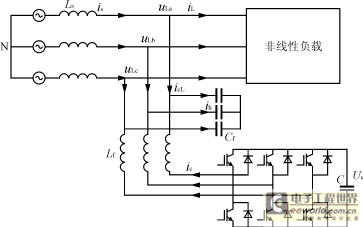
Figure 1 Main circuit structure of three-phase active filter
According to the different detection currents, the traditional control methods of parallel active power filters are divided into three types: one is the load current detection method, in which the input signal of the command current operation circuit comes from the load current, which is the most basic control method; another is the grid side current detection method; and another is a combination of the above two methods to obtain a composite control method. [1]
In order to solve the resonance and current and voltage distortion problems caused by the high-pass filter, three control methods are analyzed by using the system transfer function structure diagram, as shown in Figures 2, 3, and 4. In the figure, GI(s) is the transfer function of the command current operation circuit, which takes the current to be detected, such as the load current iL, the power supply current is, or the sum of the two as input, and the command compensation current
![]() as output. GA(s) is the transfer function of the tracking and driving circuit, which takes the command compensation current
as output. GA(s) is the transfer function of the tracking and driving circuit, which takes the command compensation current
![]() as input and the actual compensation current ic as output. GZ(s) is the transfer function of the passive high-pass filter, which takes the sum of the load current iL and the compensation current icL as input, and the power supply current is as output. G(s) is the transfer function of the series correction differential link added to prevent oscillation.
as input and the actual compensation current ic as output. GZ(s) is the transfer function of the passive high-pass filter, which takes the sum of the load current iL and the compensation current icL as input, and the power supply current is as output. G(s) is the transfer function of the series correction differential link added to prevent oscillation.

Figure 2 Structure diagram of load current detection control method

Figure 3 Structure diagram of the current control method for detecting the grid side
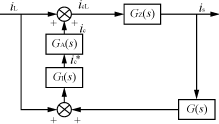
Figure 4 Composite control structure diagram
The load current detection method is adopted, and it can be seen from Figure 2 that this method is feedforward control. Although this method is very effective in controlling the controlled quantity, without the feedback of IS, as an open-loop system, it cannot solve the problem of grid-side current and common connection point voltage distortion caused by system resonance.
Using the grid-side current detection control method, the active filter is a closed-loop system, and the resonant part GZ(s) is also included in the closed loop. Therefore, adding a proportional differential link G(s) to improve dynamic performance in the control algorithm can eliminate some oscillations, and the effect is better than the previous one, but it is still not ideal. In addition, the introduction of the proportional differential link weakens the stability of the system and may cause system instability.
The compound control method is essentially to add the feedback control of the grid-side current to the first method, which becomes a feedforward-feedback compound system. Among them, the feedforward control plays a leading role, and the feedback control is mainly used to suppress resonance and improve control accuracy. This method has the advantages of the first two methods and the effect is relatively ideal, but the control algorithm is also relatively complex. Therefore, it is conceivable to improve the first two methods to obtain a control method that avoids the more complex algorithm compilation and can achieve better results.
Analyzing the first two methods, the reason why the load current detection method cannot suppress oscillation is that the passive filter GZ(s) link that generates oscillation is not controlled. The reason why the grid-side current detection control method is not very effective even if the correction link is added is that in order to obtain a good compensation effect, the proportional differential link must have a large gain. The stability of the system and the accuracy of control require a relatively small gain. This contradiction affects the final effect. In order to avoid this contradiction, directly controlling the passive filter can suppress oscillation and improve the quality of control. This paper proposes a new control method, that is, detecting the passive high-pass filter current, and adding a local feedback control method to the first two control methods.
3 Principle Analysis of New Control Method
Figure 5 is the schematic diagram of the active filter obtained by applying the method proposed in this paper to improve the traditional grid-side current control method. The basic principle of this control method is to make the active power filter generate a compensation current that is equal to the oscillating current in the passive high-pass filter and opposite in direction, thereby effectively suppressing system oscillations and eliminating current and voltage distortion. This is the same as the principle of the active power filter eliminating harmonics in the grid-side current. Since the current passing through the high-pass filter is relatively small compared to the grid-side current, 1% to 10% of the current ih of the passive high-pass filter can be directly taken as the signal current to suppress the oscillation of the high-pass filter
![]() , and added to the compensation reference signal generated by the command current operation circuit
, and added to the compensation reference signal generated by the command current operation circuit
![]() to obtain the corrected reference current. Then the compensation current is determined by the current tracking control circuit, the drive circuit, and finally by the on-off of the high-frequency switching device.
to obtain the corrected reference current. Then the compensation current is determined by the current tracking control circuit, the drive circuit, and finally by the on-off of the high-frequency switching device.
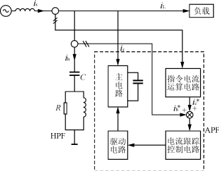
Figure 5 Schematic diagram of active filter after improving the current control method on the grid side
The structure of the improved control method is shown in Figures 6 and 7. In the figure, G1(s) and G2(s) are the transfer functions of the passive filter with icL and ih as input and ih and is as output respectively. Since the system itself contains differential components, it is easy to oscillate and is sensitive to interference signals. The use of local feedback can not only improve the steady-state performance and transient performance of the system in series correction, but also suppress the influence of resonant interference signals. At the same time, the local feedback mainly acts on the high-pass filter and has little effect on other parts. In addition, due to the introduction of this feedback, the gain of the forward channel is reduced and the stability of the system is improved. Compared with the three methods introduced above, it can not only eliminate oscillations and filter high-frequency harmonics, but also has a relatively simple structure, does not require complex algorithms, and is very easy to implement.
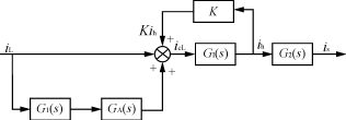
Figure 6 Structure diagram of improved load-side current control method
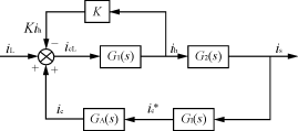
Figure 7 Structure diagram of improved current control method for detecting grid side
4 Simulation Results Analysis
The above analysis can be verified from the simulation results using PSPICE.
In the simulation, the grid frequency is 50Hz, and the operating frequency of the three-phase active power filter switch device is 20kHz. The nonlinear load is a three-phase rectifier, followed by a 20mH inductor and a 2Ω resistor. The high-pass filter uses a 50μF capacitor. The simulation results are shown in Figures 8, 9, 10, 11 and Table 1.
Table 1 Comparison of simulation results of two traditional control methods before and after improvement
| Control method | Grid side current distortion rate | Common point voltage distortion rate |
|---|---|---|
| When no compensation | 23.5% | 7.90% |
| Detection load current control method | 8.66% | 9.22% |
| Detection of grid-side current control mode | 5.06% | 5.52% |
| Improved detection load current control method | 1.82% | 2.78% |
| Improved detection of grid-side current control method | 1.61% | 3.33% |
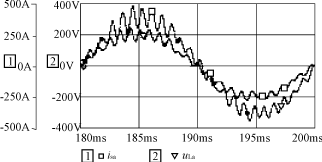
Figure 8 Grid-side current and load voltage under traditional load current detection control method
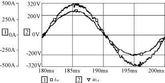
Figure 9 Grid-side current and load voltage under improved detection load current control mode
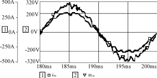
Figure 10 Grid-side current and load voltage under traditional grid-side current control method
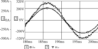
Figure 11 Grid-side current and load voltage under improved grid-side current control mode
It can be seen from Table 1 that the distortion rate of the grid-side current and the common point voltage is effectively reduced after the original control method is improved. Comparing Figures 8 and 9, Figures 10 and 11 also show that the waveforms of the grid-side current and the common point voltage of the active filter have been greatly improved after the control method is improved, and are closer to the sine shape. In short, the performance of the active filter has been greatly improved.
5 Conclusion
From the previous analysis and simulation results, it can be seen that the new control method proposed in this paper not only eliminates oscillation and filters harmonics, but also improves the stability of the system. The control algorithm is also extremely simple and has good promotion value. The disadvantage is that the number of current signals that need to be detected increases.
Previous article:Limited Bipolar Control ZVZCSPWM Full-Bridge Converter
Next article:A control method for eliminating oscillation of active power filter system
- Popular Resources
- Popular amplifiers
- Molex leverages SAP solutions to drive smart supply chain collaboration
- Pickering Launches New Future-Proof PXIe Single-Slot Controller for High-Performance Test and Measurement Applications
- CGD and Qorvo to jointly revolutionize motor control solutions
- Advanced gameplay, Harting takes your PCB board connection to a new level!
- Nidec Intelligent Motion is the first to launch an electric clutch ECU for two-wheeled vehicles
- Bosch and Tsinghua University renew cooperation agreement on artificial intelligence research to jointly promote the development of artificial intelligence in the industrial field
- GigaDevice unveils new MCU products, deeply unlocking industrial application scenarios with diversified products and solutions
- Advantech: Investing in Edge AI Innovation to Drive an Intelligent Future
- CGD and QORVO will revolutionize motor control solutions
- Innolux's intelligent steer-by-wire solution makes cars smarter and safer
- 8051 MCU - Parity Check
- How to efficiently balance the sensitivity of tactile sensing interfaces
- What should I do if the servo motor shakes? What causes the servo motor to shake quickly?
- 【Brushless Motor】Analysis of three-phase BLDC motor and sharing of two popular development boards
- Midea Industrial Technology's subsidiaries Clou Electronics and Hekang New Energy jointly appeared at the Munich Battery Energy Storage Exhibition and Solar Energy Exhibition
- Guoxin Sichen | Application of ferroelectric memory PB85RS2MC in power battery management, with a capacity of 2M
- Analysis of common faults of frequency converter
- In a head-on competition with Qualcomm, what kind of cockpit products has Intel come up with?
- Dalian Rongke's all-vanadium liquid flow battery energy storage equipment industrialization project has entered the sprint stage before production
- Allegro MicroSystems Introduces Advanced Magnetic and Inductive Position Sensing Solutions at Electronica 2024
- Car key in the left hand, liveness detection radar in the right hand, UWB is imperative for cars!
- After a decade of rapid development, domestic CIS has entered the market
- Aegis Dagger Battery + Thor EM-i Super Hybrid, Geely New Energy has thrown out two "king bombs"
- A brief discussion on functional safety - fault, error, and failure
- In the smart car 2.0 cycle, these core industry chains are facing major opportunities!
- The United States and Japan are developing new batteries. CATL faces challenges? How should China's new energy battery industry respond?
- Murata launches high-precision 6-axis inertial sensor for automobiles
- Ford patents pre-charge alarm to help save costs and respond to emergencies
- New real-time microcontroller system from Texas Instruments enables smarter processing in automotive and industrial applications
- Is this the worst impedance processing you have ever encountered?
- For large project files containing nios, timing constraints, and layout and routing, modify the internal module names and some variable names.
- Send a WDS configuration software for SI4463
- LM1875 Op Amp
- OpenBLT is an open source bootloader with comprehensive functional information, supporting USB, CAN, 232 and TCP/IP
- About the Minimum System
- Quick Start on RISC-V Architecture and Embedded Development
- There is a difference between the MSP430FR2111 official website routine and the actual running results
- Today, some web pages are black
- Download Gift|ADI System Solution Selection (Summary)

 LPC661MDA


 京公网安备 11010802033920号