Non-contact measurement of object displacement is one of the important development directions of displacement measurement technology. This is because non-contact measurement methods have the advantages of high speed and no contact with the object being measured. Traditional contact displacement sensors use potentiometer displacement sensors, which convert mechanical displacement into resistance or voltage output that is linear or has an arbitrary function relationship with it through potentiometer elements [1]. Potentiometers designed for the purpose of measuring displacement require a definite relationship between displacement change and resistance change. There are many types of non-contact displacement sensors, such as time-grid displacement sensors [2], linear displacement differential sensors [3], capacitive grid displacement sensors [4], inductive displacement sensors [5], etc. These sensors have high accuracy, but complex structures and high costs. They also impose restrictions on the movement speed of the object being measured, such as smooth operation, no sudden changes, and relatively low speed.
From the perspective of engineering application, this paper designs a displacement sensor based on magnetic sensitive technology, which has successfully improved the accuracy, shock resistance, durability and other aspects of the sensor.
1 Working principle of magnetic sensor
In the displacement sensor based on magnetic sensitive technology, MLX90316 is selected as the acquisition of magnetic sensitive angle.
The MLX90316 is a linear Hall chip that adds an integrated magnetic field concentrator (IMC) to a Hall effect sensor[6]. It can sense all three components of magnetic flux at a single point, so it can obtain a 360° rotational position value, output a highly accurate linear absolute position signal through multiple modes, and is low-cost and easy to install. Ordinary horizontal (or planar) Hall sensors can only sense magnetic flux perpendicular to the IC surface.
The front end of the MLX90316 chip is a sensor using Triaxis Hall technology. The two orthogonal analog signals obtained by the Hall sensor are amplified and processed, and then enter the chip microprocessor (DSP) through a 14-bit differential A/D converter. After being processed by the 16-bit DSP, the digital signal is divided into three outputs. The MLX90316 output has 12-bit angle resolution and 10-bit angle accuracy, and can avoid the influence of external temperature changes on output accuracy to a certain extent. The MLX90316 has three outputs: analog output converted from 12-bit D/A; PWM output with a frequency of 100 Hz to 1 000 Hz; and serial communication protocol output (SPI) in digital mode.
In this design, SPI interface output is selected.
2 Hardware interface circuit design
The displacement sensor based on magnetic sensitive technology is mainly composed of three parts: front-end angle signal acquisition, data processing unit, and data communication unit. The specific functional block diagram is shown in Figure 1.

The magnetic angle sensor uses MLX90316, which converts the angle of rotation of the magnetic field caused by the displacement into the magnetic angle.
The microprocessor unit communicates with MXL90316 through the SPI interface to complete the reception of the magnetic angle data. Since the received angle is the angle of magnetic field conversion, the magnetic angle is converted into the displacement of the wire by establishing a mathematical model and combining factors such as the hub diameter. All tasks of the sensor are ultimately run on the real-time operating system μC/OS-II. Therefore, not only the internal resources of the microcontroller should be considered, but also its portability and scalability. LPC2136 is a 32-bit ARM7TDMI-S microprocessor produced by Philips [7], embedded with 256 KB high-speed Flash memory. It adopts a three-level pipeline technology, and instruction fetching, decoding and execution are carried out simultaneously, which can process instructions in parallel and improve the CPU running speed. Due to its very small size and extremely low power consumption, it has strong anti-interference ability and is suitable for various industrial controls.
The data communication unit is designed with a RS485 communication interface, which is responsible for receiving commands from the application system and returning the collected displacement results to the application system.
2.1 SPI interface circuit design
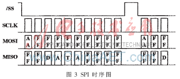
MLX90316 has 1 SPI interface for angle signal data. Since the output signal of serial communication comes directly from the internal DSP output, the SPI output mode is more stable, with smaller errors and higher anti-interference ability. In this design, the SPI interface is selected. The specific hardware interface connection circuit is shown in Figure 2. In Figure 2, the SPI 3 lines of MLX90316 are connected to the SPI0 port of LPC2136. The SPI (Serial Protocol Interface) bus interface is a synchronous serial peripheral interface. This is a serial interface protocol with 4 signal lines, including master and slave modes. The 4 signal lines are: clock line (SCK), data input line (MISO), data output line (MOSI) and slave enable line (/SS).

In the SPI interface, LPC2136 is used as the master and MLX90316 is used as the slave. The SPI communication module mainly allows LPC2136 to read the magnetic sensitivity angle of MLX90316. The SPI communication process is as follows: the master first outputs a 0xAA and a 0xFF as the communication start signal, and then outputs 8 0xFFs, while the slave will simultaneously output 2 0xFFs, 4 B angle signals and 4 0xFFs, thus completing a data communication. The specific communication timing is shown in Figure 3.

2.2 RS485 communication interface circuit design
The RS485 bus has been widely used in industrial control systems due to its many advantages, such as simple structure, high communication rate, and long transmission distance. It uses balanced transmission and differential reception to achieve communication. The transmitter converts the TTL level signal of the serial port into two differential signal outputs, A and B. After cable transmission, the differential signal is restored to a TTL level signal at the receiver [8]. Since the transmission line usually uses twisted pair cables and differential transmission, it has a strong ability to resist common mode interference, and the bus transceiver has a high sensitivity.
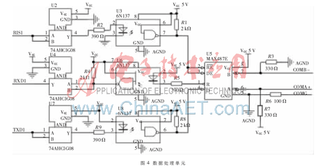
An RS485 signal output is designed in the displacement sensor based on magnetic sensitive technology. The RS485 interface chip uses MAX3485 to exchange displacement data with the application system. As shown in Figure 4, in order to ensure the reliability of data communication, the communication interface uses the photoelectric isolation chip 6N137.

3 Implementation of displacement calculation algorithm
MLX90316 collects the rotation angle data, and ARM calculates the linear displacement data by establishing a mathematical model based on the acquired angle data. ARM communicates with the device of the application system through the RS485 communication interface, receives commands from the application system device, and feeds back the collected displacement signal to the application system.
The displacement calculation formula is:

where R is the linear displacement distance causing the angular transformation of MLX90316, the center radius of the angular transformation, φ is the angle of rotation of MLX90316 caused by the linear displacement, and L is the linear displacement.
4 Engineering Application and Conclusion
(1) Magnet selection
Any magnet with uniform horizontal magnetic flux can be used. The size and material of the magnet are not critical. The horizontal magnetic flux must be within the range of 20-70 mT (e.g., 45 mT ± 25 mT) within mechanical, magnetic field and thermal tolerances.
(2) Air gap distance
In terms of air gap, if the actual air gap from the IC surface is greater than 7.5 mm, a ring magnet is better than a disc magnet. The magnet can be placed at the end of the shaft, and when using a ring magnet, it can be wrapped around the shaft. Special magnet designs can also be used to obtain normal transmission characteristics of the rotary position sensor.
In the "Intelligent Detection System of Dam Displacement Based on FPGA Technology", this sensor is used to collect the displacement of the dam root stone. The 35 monitoring points are connected into a star network using the RSS485 bus. From the test results, it can be seen that this sensor overcomes the shortcomings of traditional wire-type displacement sensors such as easy wear, poor resolution, low resistance, and poor high-frequency characteristics, and improves the measurement accuracy.
Previous article:Analysis of Lightning Protection Control in Petrochemical Instrumentation System
Next article:Overview and measurement principle of radio frequency admittance level meter
- Molex leverages SAP solutions to drive smart supply chain collaboration
- Pickering Launches New Future-Proof PXIe Single-Slot Controller for High-Performance Test and Measurement Applications
- CGD and Qorvo to jointly revolutionize motor control solutions
- Advanced gameplay, Harting takes your PCB board connection to a new level!
- Nidec Intelligent Motion is the first to launch an electric clutch ECU for two-wheeled vehicles
- Bosch and Tsinghua University renew cooperation agreement on artificial intelligence research to jointly promote the development of artificial intelligence in the industrial field
- GigaDevice unveils new MCU products, deeply unlocking industrial application scenarios with diversified products and solutions
- Advantech: Investing in Edge AI Innovation to Drive an Intelligent Future
- CGD and QORVO will revolutionize motor control solutions
- Innolux's intelligent steer-by-wire solution makes cars smarter and safer
- 8051 MCU - Parity Check
- How to efficiently balance the sensitivity of tactile sensing interfaces
- What should I do if the servo motor shakes? What causes the servo motor to shake quickly?
- 【Brushless Motor】Analysis of three-phase BLDC motor and sharing of two popular development boards
- Midea Industrial Technology's subsidiaries Clou Electronics and Hekang New Energy jointly appeared at the Munich Battery Energy Storage Exhibition and Solar Energy Exhibition
- Guoxin Sichen | Application of ferroelectric memory PB85RS2MC in power battery management, with a capacity of 2M
- Analysis of common faults of frequency converter
- In a head-on competition with Qualcomm, what kind of cockpit products has Intel come up with?
- Dalian Rongke's all-vanadium liquid flow battery energy storage equipment industrialization project has entered the sprint stage before production
- Allegro MicroSystems Introduces Advanced Magnetic and Inductive Position Sensing Solutions at Electronica 2024
- Car key in the left hand, liveness detection radar in the right hand, UWB is imperative for cars!
- After a decade of rapid development, domestic CIS has entered the market
- Aegis Dagger Battery + Thor EM-i Super Hybrid, Geely New Energy has thrown out two "king bombs"
- A brief discussion on functional safety - fault, error, and failure
- In the smart car 2.0 cycle, these core industry chains are facing major opportunities!
- Rambus Launches Industry's First HBM 4 Controller IP: What Are the Technical Details Behind It?
- The United States and Japan are developing new batteries. CATL faces challenges? How should China's new energy battery industry respond?
- Murata launches high-precision 6-axis inertial sensor for automobiles
- Ford patents pre-charge alarm to help save costs and respond to emergencies
- More images of the sensor suite
- CAN bus and its application technology
- Problems with optocoupler measurements
- Is the clock in CCS accurate in measuring program running time?
- The ballast is broken, and I want to change to a DC switching power supply. Could you please tell me what voltage is appropriate?
- Introduction to RT-Thread system kernel
- How to use the cursor function to measure pulse signals? Duoduoluo invites you to learn together! ヾ(^^)
- Configuration and use of TMS320F28379D SCID SCIB
- How to set I2C1 on GD32E230C development board?
- power supply

 【Maxim】71M6545HT-71M6545T Multi-Phase Smart Meter Processor


 京公网安备 11010802033920号