The stepper motor is an open-loop servo motion system actuator that is controlled in a pulse manner and outputs angular displacement. Compared with AC servo motors and DC servo motors, its outstanding advantages are low price and no accumulated error. However, there are many shortcomings in the operation of stepper motors, such as low-frequency oscillation, high noise, low resolution, etc., which seriously restrict the application range of stepper motors. The operating performance of a stepper motor is closely related to its driver, and the shortcomings of the stepper motor can be overcome through improvements in drive technology. Compared with other driving methods, the subdivision driving method can not only reduce the step angle of the stepper motor and improve the resolution, but also reduce or eliminate low-frequency vibration, making the motor run more smoothly and evenly. Overall, segment-driven control works best. Because commonly used low-end stepper motor servo systems do not have encoder feedback, as the motor speed increases, its internal control current decreases accordingly, resulting in lost steps. Therefore, it is widely used in fields where speed and accuracy are not high.
Because the three-phase hybrid stepper motor has better low-speed stability and output torque than the two-phase stepper motor, the three-phase hybrid stepper motor has better application prospects than the two-phase stepper motor. Traditional three-phase hybrid stepper motor
2. Segmentation principle
Essentially, the subdivision control of a stepper motor is to control the current in the stator winding of the stepper motor so that the synthetic magnetic field inside the stepper motor changes according to certain requirements, thereby achieving the subdivision of the step angle of the stepper motor. . The best subdivision method is the subdivision of constant torque and equal step angle. Generally speaking, the amplitude of the synthetic magnetic field vector determines the size of the motor's rotational torque, and the angle between two adjacent synthetic magnetic field vectors determines the size of the step angle. A nearly uniform circular rotating magnetic field is generated in the motor. The synthetic magnetic field vector of each phase winding, that is, the synthetic vector of the current of each phase winding, should rotate in space with constant amplitude. This requires passing through each phase winding. sinusoidal current.
The working principle of the three-phase hybrid stepper motor is very similar to the AC permanent magnet synchronous servo motor. The permanent magnets used on the rotor are also rare earth permanent magnet materials with high magnetic density, so the influence of the induced current generated on the rotor on the rotor magnetic field is negligible. Structurally, it is equivalent to a multi-pole AC permanent magnet synchronous motor. Since the input is a three-phase sinusoidal current, the generated spatial magnetic field is circularly distributed, and the structural model of a permanent magnet synchronous motor (Figure 1) can be used to analyze the torque characteristics of the three-phase hybrid stepper motor. To facilitate analysis, the following assumptions can be made:
a. The three-phase windings of the motor stator are completely symmetrical;
b. Magnetic saturation, eddy current and core loss are ignored;
c. There is no dynamic response process to the excitation current.

Figure 1 Simple structural model of three-phase permanent magnet synchronous motor
U, V, and W are the three coil windings on the stator, and the axes of the three coil windings are 120°. When the single-phase winding of the motor is energized, the steady-state torque can be expressed as: T=f(i,theta). Among them, i is the current passing through the winding; theta is the angle of the motor rotor from the reference point. Since the magnetic saturation effect is negligible and the rotor structure is circular, its angular characteristics are strictly sinusoidal,
That is: T=k *I*sin (theta), k is the torque constant.
If the ideal current source supplies the motor winding with three-phase balanced current iU, iV, iW with a constant amplitude of I, that is:
iU=I*sin(wt)
iV=I*sin(wt+2*PI/3)
iW =I*sin(wt+4*PI/3)
Then the steady-state torque generated by each phase current of the motor is:
TU=k*I*sin(wt)*sin(theta)
TV=k*I*sin(wt+2*PI/3)*sin(theta+2*PI/3)
TW=k*I*sin( wt+4*PI/3)*sin(theta+4*PI/3)
During steady-state operation, theta=wt, then the resultant torque generated by the three-phase winding is:
T=TU+TV+TW=3/2*k*I*sin(PI/2-wt+theta)=3/2*k*I The
above analysis shows that for a three-phase permanent magnet synchronous motor, when the three-phase winding When a sinusoidal current with a phase difference of 120° is input, the output torque of the motor is constant due to the internal circular rotating magnetic field. Therefore, the AC servo control principle is applied to the three-phase hybrid stepper motor drive system. The input 220V AC is converted into DC after rectification, and then converted into three-way stepped sinusoidal waveform current through pulse width modulation technology. The fixed timing sequence flows through the three windings respectively, and each step corresponds to one step of the motor rotation. The motor speed is changed by changing the frequency of the sinusoidal current output by the driver, and the number of output steps determines the angle of each step. When the angle is smaller, the number of steps is greater, that is, the subdivision is larger, from Theoretically speaking, this angle can be set small enough, so the number of subdivisions can be very large. The angle of each step of the AC servo control has a great relationship with the accuracy of the feedback encoder. Generally, 2500 lines are used, so The angle turned by each step is only 0.144 degrees. For the stepper motor controlled by this method, for example, if its subdivision is 10000, the angle turned by each step is 0.036 degrees, so the accuracy is much higher than that of ordinary servo control. Of course, when the stepper motor rotates, the inductance of each phase winding of the motor will form a reverse electromotive force. The higher the frequency, the greater the reverse electromotive force. Under its action, the phase current of the motor decreases as the frequency (or speed) increases, resulting in a decrease in torque. Through the constant current method, the same phase current can be maintained at low and high frequencies of the motor.

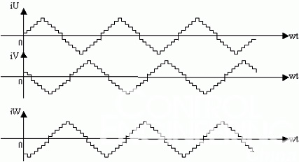
Figure 2 shows three-phase stepped sinusoidal currents with a phase difference of 120°.
Three-phase hybrid stepper motors generally connect the three-phase windings in a star or triangle shape. According to the basic circuit theorem, the sum of the three-phase currents is zero. That is IU+IV+IW =0. Therefore, it is usually only necessary to generate the given signal of the two-phase winding, and the given signal of the third-phase winding can be obtained from the other two phases. Similarly, only the actual currents of the corresponding two-phase windings need to be sampled, and the actual current of the third-phase winding can be obtained according to Eq.
3. System composition of three-phase hybrid stepper motor driver
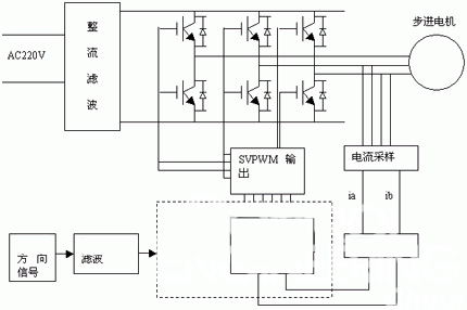
The overall scheme of the driver is shown in Figure 3, which mainly consists of a single-chip microcomputer circuit, a current tracking SPWM circuit and a power drive circuit.

Figure 3 Overall block diagram of the driver
3.1 DSP module design
Here, we chose TI's DSP as the CPU chip. DSP (Digital Signal Processor) is actually a single-chip microcomputer. It also integrates the central processing unit, control unit and peripheral devices onto one chip. But it has its own distinctive characteristics - because it uses multiple sets of bus technology to realize parallel operation of the machine mechanism, thus greatly improving the computing speed, it has stronger computing power and better real-time performance. The DSP (TMS320LF2407A) selected in this article is a motor control-specific chip with 144 pins, rich IO resources, four general-purpose timers, and two PWM generators dedicated to controlling three-phase motors (can generate six PWM signal), and there are also dedicated I/O ports for receiving external pulses and directions, thus simplifying circuit design and program development.
DSP input signals include step pulse signal CP, direction control signal, offline signal, and overcurrent protection signal. These signals are connected to the pins of the DSP through high-speed optocouplers, and there are also subdivision step numbers and current selection signals. When the offline signal is valid, the current output from the driver to the motor is cut off, and the motor rotor is in a free state (offline state). The feedback current is sampled through the 10-bit analog-to-digital converter (AD) that comes with the DSP. After the feedback current passes through a certain algorithm, the motor is controlled by the PWM port output of the DSP. 3.2 Current tracking loop
This transmission method uses the amplitude of the analog voltage to represent the size of the sampling current or voltage. It is mainly used to sample the a and b phase currents and bus voltage detection to achieve motor current control and overvoltage, undervoltage, and overcurrent protection. The driver detects the actual current of the stepper motor winding through the sampling resistor, compares it with the set current and then passes through the hysteresis comparator regulator. The regulator output signal is output by a triangular wave carrier with a frequency of 20KHz to form a pulse width modulation signal (PWM). The power drive interface circuit controls the turn-on and turn-off of high-power semiconductor devices, so that the actual winding current of the stepper motor tracks the given reference signal and changes according to the given sinusoidal law.
3.3 Power drive circuit
The main circuit of the driver adopts the form of AC-DC-AC voltage inverter, which is composed of rectifier filter circuit, three-phase inverter and stepper motor. The rectifier and filter circuit forms a DC voltage source to complete the conversion of 220V, 50Hz AC power to DC power. The inverter converts DC power into variable frequency AC power and provides the required AC current for the stator winding of the three-phase hybrid stepper motor. The inverter is composed of six G30N60B3DMOS tubes produced by Fairchild Company, forming a three-phase inverter bridge. The driver uses two resistors to detect the instantaneous value of the stepper motor phase current.
The core of the power drive circuit is the power module (MOS tube). The MOS tube and the current tracking PWM output must be connected through a dedicated high-speed optocoupler. Select a suitable MOS tube based on the overcurrent value of the MOS tube and the peak line current of the motor, that is, the peak value of the motor's line current is less than the maximum current value of the MOS tube. The maximum phase current of the motor in this design is 8.1A, which is the effective value of the phase current. The peak phase current is 8.1* sqrt(2) = 11.312A. In addition, when the motor winding is connected in delta, the line current is 3 times the phase current, so the peak line current is 19.6A. According to the G30N60B3DPDF document, its maximum flow value is 30A, so normal use can be guaranteed. Normal operation requires appropriate heat dissipation design to ensure that the internal junction temperature is always less than 150 degrees Celsius. Therefore, an external radiator and forced air cooling are required to ensure the normal operation of the MOS tube. .
3.4 Parallel port communication
In order to avoid losses caused by power outages or other special reasons during the control process, live RAM is used to store the motor position to ensure that the workpiece can continue to be processed after power is supplied. and
3.5 Control software process

Figure 4 Main program flow chart

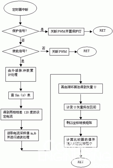
Figure 5 Flow chart of the interrupt part
In order to reduce power consumption and protect the motor, an automatic half-flow function is set up, which is automatically adjusted by a hysteresis comparator.
4 Conclusion
Practice has proved that the driving method discussed in this article is highly adaptable and can basically adapt to all three-phase hybrid stepper motors. Especially for the three-phase winding star connection method, the operation is smooth at low frequency without oscillation, which effectively suppresses oscillation and noise. In addition, a variety of protection circuits are designed inside the driver, which greatly improves the reliability of the entire driver.
Previous article:Field-oriented control of brushless motors using an ARM7 processor
Next article:Design of three-phase hybrid multi-subdivision stepper motor driver
- Popular Resources
- Popular amplifiers
- Molex leverages SAP solutions to drive smart supply chain collaboration
- Pickering Launches New Future-Proof PXIe Single-Slot Controller for High-Performance Test and Measurement Applications
- CGD and Qorvo to jointly revolutionize motor control solutions
- Advanced gameplay, Harting takes your PCB board connection to a new level!
- Nidec Intelligent Motion is the first to launch an electric clutch ECU for two-wheeled vehicles
- Bosch and Tsinghua University renew cooperation agreement on artificial intelligence research to jointly promote the development of artificial intelligence in the industrial field
- GigaDevice unveils new MCU products, deeply unlocking industrial application scenarios with diversified products and solutions
- Advantech: Investing in Edge AI Innovation to Drive an Intelligent Future
- CGD and QORVO will revolutionize motor control solutions
- Innolux's intelligent steer-by-wire solution makes cars smarter and safer
- 8051 MCU - Parity Check
- How to efficiently balance the sensitivity of tactile sensing interfaces
- What should I do if the servo motor shakes? What causes the servo motor to shake quickly?
- 【Brushless Motor】Analysis of three-phase BLDC motor and sharing of two popular development boards
- Midea Industrial Technology's subsidiaries Clou Electronics and Hekang New Energy jointly appeared at the Munich Battery Energy Storage Exhibition and Solar Energy Exhibition
- Guoxin Sichen | Application of ferroelectric memory PB85RS2MC in power battery management, with a capacity of 2M
- Analysis of common faults of frequency converter
- In a head-on competition with Qualcomm, what kind of cockpit products has Intel come up with?
- Dalian Rongke's all-vanadium liquid flow battery energy storage equipment industrialization project has entered the sprint stage before production
- Allegro MicroSystems Introduces Advanced Magnetic and Inductive Position Sensing Solutions at Electronica 2024
- Car key in the left hand, liveness detection radar in the right hand, UWB is imperative for cars!
- After a decade of rapid development, domestic CIS has entered the market
- Aegis Dagger Battery + Thor EM-i Super Hybrid, Geely New Energy has thrown out two "king bombs"
- A brief discussion on functional safety - fault, error, and failure
- In the smart car 2.0 cycle, these core industry chains are facing major opportunities!
- The United States and Japan are developing new batteries. CATL faces challenges? How should China's new energy battery industry respond?
- Murata launches high-precision 6-axis inertial sensor for automobiles
- Ford patents pre-charge alarm to help save costs and respond to emergencies
- New real-time microcontroller system from Texas Instruments enables smarter processing in automotive and industrial applications
- ESP-S3-12K (IV) ---- Here comes the ESP-box effect
- Pre-registration for the prize live broadcast: ADI's vital signs monitoring solutions in wearable products
- Fun Oscilloscope + Plot Heart
- Timer T0 controls the running light
- [Review of SGP40] Rapid deployment of AI ambient air quality tracking model #3 I2C and UART interface selection
- [Silicon Labs BG22-EK4108A Bluetooth Development Evaluation] Development Environment Construction Step by Step
- Signal Generator and DA Conversion FPGA Case Tutorial
- Hardware Design Guide for TMS320F28xx and TMS320F28xxx DSCs
- 28335 floating point performance test
- What's your Chinese character of the year?

 Dual Radar: A Dual 4D Radar Multimodal Dataset for Autonomous Driving
 Digilent Vivado library


 京公网安备 11010802033920号