Abstract: PID regulating instrument and sensor can be used together to measure and display the temperature of bell-type furnace on steel product production line. Through the corresponding actuator, PID regulation and control, alarm control, data acquisition and recording of relevant bell-type furnace equipment can be realized. However, for the field environment with multiple production lines and each production line using multiple PID regulating instruments, it is not convenient to operate each instrument in turn. Borland C ++ Builder 6 is used to design an online centralized monitoring system for PID regulating instruments. Using the powerful graphical control interface of Borland C ++ Builder 6 and the SPComm control to program under the serial port, the real-time monitoring and remote control of each partition instrument on the production line are well realized through the USB to RS485 protocol converter.
1 Introduction
In order to effectively realize the real-time monitoring and remote control of the instrument data of each partition on the production line, Borland C++ Builder6 was used to design the PID control instrument online centralized monitoring system through the USB to RS485 protocol converter. It mainly includes: the temperature monitoring system of the bell-type furnace equipment on the steel product production line, the database system, and the reading and writing data system of the PID control instrument.
2 Overall structure of monitoring system
The monitoring system adopts RS485 bus structure, and realizes network communication between the host computer and the PID control instrument through the USB to RS485 protocol converter. The characteristics of RS485 bus are simple and convenient implementation. Through RS-485, it can be networked to form a distributed system. It allows up to 32 drivers and 32 receivers to be connected in parallel, which can fully meet the networking needs of multiple PID control instruments equipped at the production site.
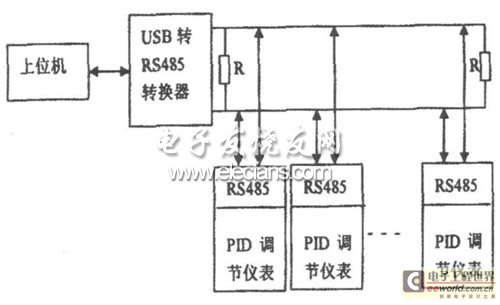
Figure 1 Overall structure of monitoring system
3 Monitoring System Hardware Design
3.1 Self-tuning expert PID control instrument
The self-tuning expert PID control instrument has a switching power supply with a wide input range of 100 ~ 240VAC. The input adopts digital correction and self-calibration technology, which makes the measurement accurate and stable, eliminating the measurement errors caused by temperature drift and time drift. The instrument fully adopts surface mount technology and adopts multiple protection and isolation design, with strong anti-interference ability and good reliability.
The instrument adopts advanced expert PID intelligent adjustment algorithm, with precise and stable control, no overshoot, and high-precision self-tuning (AT) function.
The instrument output adopts modular hardware structure design, and various control modes can be realized by replacing different functional modules. PID control output can choose 4mA ~ 20mA current, (1V ~ 5V voltage), SSR drive, single-phase/three-phase SCR zero-crossing trigger and single-phase SCR phase shift trigger, etc., and there are two alarm output functions, and optional transmission output or standard communication interface (RS485 or RS232).
The instrument has multiple types of input functions. One instrument can be equipped with different input signals (thermocouple/thermal resistor/linear voltage/linear current/linear resistance), which greatly reduces the number of spare meters. It has a wide range of applications and can be used with various sensors and transmitters to measure and display physical quantities such as temperature, pressure, liquid level, capacity, force, etc. It can also be used with various actuators to perform PID regulation and control, alarm control, data acquisition and recording on electric heating equipment and electromagnetic and electric valves.
3. 2 USB to RS485 protocol converter
The USB to RS485 protocol converter is a plug-and-play protocol converter, fully compatible with USB (Universal Serial Bus) Rev: 2.0; it supports any baud rate, data bit, stop bit, data transmission and reception time interval and other parameters, and is an adaptive protocol converter.
Support RS-232/485 interface, data transmission rate above 2Mbps.
Support automatic handshake protocol; support remote wake-up and power management; support direct power supply from USB bus, no external power supply (DC 5V) required; the driver is confirmed twice, the first time is the chip driver, the second time is the I/O port driver, and it can be completed for the drivers in the same directory.
4. Software Design of Monitoring System
The software system of the monitoring system is designed and developed using Borland C++ Builder 6. Through its powerful graphical control interface and SPComm control programmed under the serial port, the Modbus protocol is adopted, and the USB to RS485 protocol converter is used to well realize the communication function between the host computer and the PID adjustment instrument. Therefore, the parameter monitoring and remote operation control of each partition instrument on the production line can be easily realized through the operation of the host computer monitoring system interface.
The software system mainly consists of three parts: the temperature monitoring system of the bell-type furnace equipment on the steel product production line, the database system, and the reading and writing data system of the PID control instrument.
4.1 Modbus communication
The standard Modbus port is a serial interface compatible with RS-232C, which defines the connection port pins, cables, signal bits, transmission baud rate, and parity. The controller can be networked directly or via a Modem.
Controller communication uses master-slave technology, that is, the master device can initiate the transmission (query). The slave device responds accordingly based on the data provided by the master device query. Regardless of whether the master device queries or the slave device responds, each Modbus frame includes an address field, a function field, a data field, and an error detection field. Modbus communication has two modes: ASCII mode and RTU mode. Compared with ASCII mode, RTU mode can transmit more data than ASCII mode at the same baud rate.
Using RTU mode, message transmission must start with a pause interval of at least 3.5 characters. The entire message frame must be transmitted as a continuous stream. If there is a pause time of more than 1.5 characters before the frame is completed, the receiving device will refresh the incomplete message and assume that the next byte is the address field of a new message. Similarly, if a new message starts within less than 3.5 characters after the previous message, the receiving device will think it is a continuation of the previous message. This will cause an error because the value in the last CRC field cannot be correct. A typical message frame is shown in Table 1.
Table 1 RTU message frame

The PID control instrument uses Modbus-RTU mode for host computer communication. The protocol format is: 8 data bits, 1 stop bit, no check bit, and the sending and receiving data are all in hexadecimal format.
The format of the transmitted data is shown in Table 2.
Table 2 Sending data format

Among them, when the communication address of the parameter is represented by one byte, it corresponds to the A2 position, and A1 defaults to 00H; 03 and 04 instructions are both read commands, among which 04 corresponds to the read data and cannot be written. 03 and 06 instructions correspond to the parameter address, one read and one write; A1, A2 and A3, A4 form two double-byte data, CRC check code is a double-byte data, all data are high-order first and low-order last; when 03 and 04 instructions read data, A1 and A2 are the addresses to start reading, and A3 and A4 are the number of consecutively read data; in 06 instruction, A1 and A2 are the addresses to be written to the data, and A3 and A4 represent the data to be written.
Return data format, when the 06 instruction writes data, the sent and returned data are consistent; the return data format of the 03 and 04 instructions is shown in Table 3, where the number of returned data bytes is: N × 2.
Table 3 Return data format

4.2 Temperature Monitoring System
The temperature monitoring system is designed and developed using Borland C++ Builder 6, mainly involving the use of controls such as Chart, Timer, SPComm, and MainMenu. The system program design mainly includes: sampling program, data saving program, historical data backup program, etc. The main process of the temperature monitoring system is shown in Figure 2.
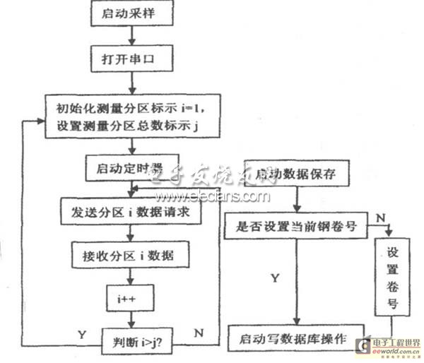
Figure 2 Main flow chart of the monitoring system
4.3 Database System
Start the database system program, first select the corresponding database file, and the corresponding database information will be displayed, as shown in Figure 3. The database system mainly includes two data retrieval methods: Method 1, search by selecting the search date; Method 2, set the volume number and search by volume number. Through the database system, you can easily browse and query historical data.
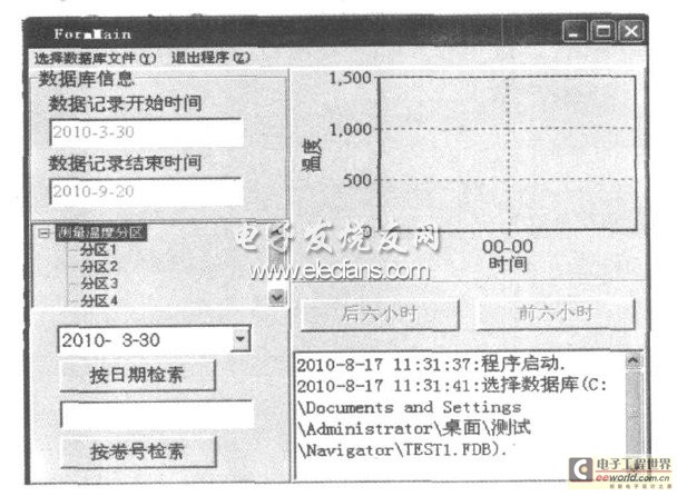
Figure 3 Database system
4.4 PID control instrument reading and writing data system
The data reading and writing system of the PID control instrument mainly includes three functions: data setting function before writing into the instrument, data writing function into the instrument and data reading function of the instrument.
Figure 4 is the main flow chart of the data writing instrument program. The data setting function is mainly realized through two ways: Path 1, add the system configuration setting file "MControlini", and realize the setting operation before writing data into the instrument by setting and modifying the temperature and time parameters in the configuration setting file; Path 2, start the data reading and writing system program, select the corresponding database file, and the system program will automatically associate the total number of partition instruments set in the database file, and realize the setting operation before writing data into the instrument by modifying and setting the temperature and time parameters of each curve segment of each partition. Among them, when setting data in Path 2, the format and size of the input data can be judged, and the reset data state changes will be displayed in real time in the corresponding curve segment of the interface.
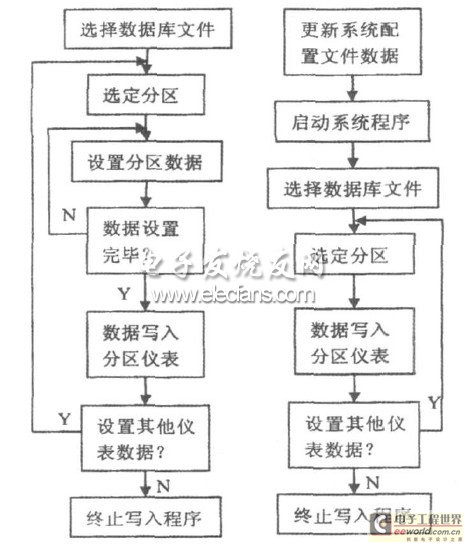
Figure 4 Main flow chart of data writing instrument program
Figure 5 is the main flow chart of the instrument data reading program. By comparing and analyzing the instrument data read by the system with the parameters in the system configuration file, it is determined whether the instrument data is consistent with the system configuration file data.
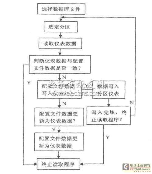
Figure 5 Main flow chart of the instrument data reading program
If "yes", it means that the parameters set by the system are very consistent with the instrument data, and the reading program is terminated; if "no", the next step of the program is executed: "write the configuration file data to the instrument" or "update the configuration file data to the instrument data". Through the instrument data reading program, the system has achieved good consistency between the configuration file data and the instrument data.
5 Conclusion
Based on RS485 bus structure and Modbus protocol, the monitoring system designed with Borland C++Builder6 can well realize real-time monitoring and remote control of instruments in each partition on the production line.
Previous article:Application of NISE series in wall cutting production line
Next article:Digital design scheme for control circuit of radar's supporting equipment
Recommended ReadingLatest update time:2024-11-16 20:40


- Popular Resources
- Popular amplifiers
-
 Siemens S7-1200-PLC Programming and Application Tutorial (3rd Edition) (Edited by Shi Shouyong)
 -
 Virtualization Technology Practice Guide - High-efficiency and low-cost solutions for small and medium-sized enterprises (Wang Chunhai)
 -
 usb_host_device_code
 -
 100 Examples of Microcontroller C Language Applications (with CD-ROM, 3rd Edition) (Wang Huiliang, Wang Dongfeng, Dong Guanqiang)
- Molex leverages SAP solutions to drive smart supply chain collaboration
- Pickering Launches New Future-Proof PXIe Single-Slot Controller for High-Performance Test and Measurement Applications
- CGD and Qorvo to jointly revolutionize motor control solutions
- Advanced gameplay, Harting takes your PCB board connection to a new level!
- Nidec Intelligent Motion is the first to launch an electric clutch ECU for two-wheeled vehicles
- Bosch and Tsinghua University renew cooperation agreement on artificial intelligence research to jointly promote the development of artificial intelligence in the industrial field
- GigaDevice unveils new MCU products, deeply unlocking industrial application scenarios with diversified products and solutions
- Advantech: Investing in Edge AI Innovation to Drive an Intelligent Future
- CGD and QORVO will revolutionize motor control solutions
- Innolux's intelligent steer-by-wire solution makes cars smarter and safer
- 8051 MCU - Parity Check
- How to efficiently balance the sensitivity of tactile sensing interfaces
- What should I do if the servo motor shakes? What causes the servo motor to shake quickly?
- 【Brushless Motor】Analysis of three-phase BLDC motor and sharing of two popular development boards
- Midea Industrial Technology's subsidiaries Clou Electronics and Hekang New Energy jointly appeared at the Munich Battery Energy Storage Exhibition and Solar Energy Exhibition
- Guoxin Sichen | Application of ferroelectric memory PB85RS2MC in power battery management, with a capacity of 2M
- Analysis of common faults of frequency converter
- In a head-on competition with Qualcomm, what kind of cockpit products has Intel come up with?
- Dalian Rongke's all-vanadium liquid flow battery energy storage equipment industrialization project has entered the sprint stage before production
- Allegro MicroSystems Introduces Advanced Magnetic and Inductive Position Sensing Solutions at Electronica 2024
- Car key in the left hand, liveness detection radar in the right hand, UWB is imperative for cars!
- After a decade of rapid development, domestic CIS has entered the market
- Aegis Dagger Battery + Thor EM-i Super Hybrid, Geely New Energy has thrown out two "king bombs"
- A brief discussion on functional safety - fault, error, and failure
- In the smart car 2.0 cycle, these core industry chains are facing major opportunities!
- The United States and Japan are developing new batteries. CATL faces challenges? How should China's new energy battery industry respond?
- Murata launches high-precision 6-axis inertial sensor for automobiles
- Ford patents pre-charge alarm to help save costs and respond to emergencies
- New real-time microcontroller system from Texas Instruments enables smarter processing in automotive and industrial applications
- New books exchanged
- DLP LightCrafter Display 2000 Evaluation Module with Embedded Linux Host Processor
- When the circuit designed with TPS40057 is powered on, a sound similar to a relay closing can be heard, and the power output is abnormal.
- The number of 5G devices has exceeded the 600 mark, and more than 150 5G networks have been launched worldwide
- MSP430 MCU debug interface and JTAG emulator schematic diagram
- VGA-OUT Circuit
- The topological classification of DCDC can be understood as follows
- HCS12 Series MC9S12DP512MPVE Microcontroller 16Bit Flash 112LQFP
- Can a PMOS be connected in series on the communication line as a switch?
- How to achieve positive and negative pulse output using a single battery power supply

 Siemens S7-1200-PLC Programming and Application Tutorial (3rd Edition) (Edited by Shi Shouyong)
 Virtualization Technology Practice Guide - High-efficiency and low-cost solutions for small and medium-sized enterprises (Wang Chunhai)
 usb_host_device_code


 京公网安备 11010802033920号