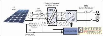
When the electricity generated by solar panels is fed back into the grid (a "grid-connected" system), two connection options are possible:
Connect the solar panel to the inverter and connect it to the grid via a transformer (Figure 1), or connect the inverter directly to the grid to avoid using a transformer (transformer-less system) (Figure 2).

Figure 1

Figure 2
Another solution is not to feed the power into the grid, but to charge batteries that are used to power automation. This is "off-grid". For remote building applications such as mining subsidence, remote subsidence in villages in Australia or Canada or third world countries, as well as road signs and underground lights.
Today, solar inverters are available on the market that handle power from 500W to 10KW, and installations up to 500KW capacity are possible, such as continuous lighting in underground parking lots of large stadiums. System service life may be up to 20 years. Both types of systems (with and without transformers) can provide a single-phase output (for smaller power systems) or a three-phase output (for high-power systems), depending on the target grid and power installation.
Two or three different inverters are used today, depending on the system design objectives, including size, weight, robustness, electrical separation from the grid, price, efficiency, and losses. To help improve efficiency and protect the system, it is important to measure the current in all types of solar inverters.
The transformerless design is the most efficient type because it does not incur transformer losses. In this configuration, a boost converter is sometimes used between the photovoltaic (PV) array and the inverter (DC/AC) to convert the module voltage to the inverter input voltage.
Maximum power point tracking (MPPT) components are usually used just after the PV array to ensure that the array operates at its maximum power operating level. Using current and voltage sensors for the tracking function, a special software algorithm is applied together with dedicated electronic components to control the operating point of the solar panel (battery). Generally, one current sensor can be used to measure the single-phase output (the current supplied to the grid) and another sensor can be used to measure the input DC current (10-25A). In the case of a three-phase output, two sensors can be used to measure the AC current of the three-phase output. The DC/AC inverter connected to the grid is a full-bridge inverter that converts the DC signal into a sine wave.
The inverter output current (15-50ARMS) flowing into the grid is measured by a sensor in order to be fed back to the controller for pulse width modulated (PWM) sine wave control. The controller is mainly based on a microprocessor or DSP (digital signal processor) that is supplied with +5V and shares the reference voltage with other active components of the electronic control system. LEM's HMS current sensor operates from a +5V supply. Its internal reference voltage (2.5V) is provided by a separate terminal, allowing the sensor to be easily used by a DSP or microprocessor. However, the sensor can also accept an external reference voltage (between 2V and 2.8V) from these same DSPs, from which the sensor obtains its own reference voltage. This symbiosis between all electronic components of the control system makes the entire application more efficient (reference drift in error calculations is eliminated). The HMS current sensor is very suitable for all current measurements required by solar inverters.
Current sensors can be used for peak current detection, for comparison of the actual value with the set point. Inverters also use current sensors in systems that control the output frequency. In fact, whenever the frequency moves out of the preselected range, the inverter stops operating for a short while (less than two seconds).
Since low DC values that must not be exceeded are required on the grid (AC side), offset and temperature drift must be as good as possible. Another requirement for the grid connection is that no DC currents can be fed into the grid. DC currents generated by sensor offsets or IGBT communication can cause network problems. This current can saturate the transformer, which in turn generates more losses and more harmonics in the network. For transformerless configurations, this is not a big problem.
Although each country has its own different acceptance values, the common requirement is 0.5% or 1% of the nominal output current, or in some countries a limit value (20mA in the UK, 1A in Germany and the Benelux, 100mA in Japan, 50mA in China and the United States). If the DC current is greater than this limit, the system must be disconnected from the grid. There is no clear definition as to whether the DC current needs to be measured or just the critical value is detected.
In future solar designs, this current may be compensated. The DC component is calculated by measuring the average value of the AC current; this represents the DC component. Therefore, the DC offset of the current sensor used in the inverter control loop should be as low as possible. Also, the DC offset due to inverter IGBT switching delays should be avoided or minimized. This DC offset can lead to saturation of the network distribution transformer. New inverter topologies are being developed to reduce this DC offset.
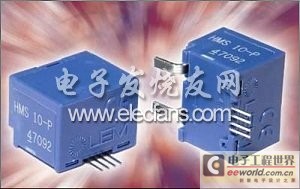
The dimensions of the HMS current sensor are only 16 (length) x 13.5 (width) x 12 (height) mm.

Furthermore, when space on the PCB for current measurement is tight, it is ideal to integrate the primary conductor. Surface mounting these modules directly onto the PCB reduces manufacturing costs while also avoiding the confusion of various soldering processes. In addition to its small form factor, the HMS design also achieves 8mm creepage and clearance distances. The HMS has high isolation performance (test isolation voltage: 4.3 kVRMS/50 Hz/1 minute) accumulated through a 600 CTI in its plastic case.
Four standard modules are available covering nominal AC, DC, pulsed and mixed isolated current measurements, which can measure 5, 10, 15 or 20 ARMS currents up to 50kHz over a wide measurement range of ± 3 x IPN. The mechanical design of the four modules is exactly the same, so the modules can be used to measure currents across the entire end product range. Gain and offset are fixed and set so that at lpn, the output voltage is equal to the input or output reference voltage ± 0.625 V.
A unique LEM ASIC designed for use with open-loop Hall-effect technology has been used to improve performance. These performance improvements include better offset and gain drift and linearity, in addition to a wider operating temperature range (-40 to +85°C) compared to traditional discrete technologies.
The sensor is CE marked and complies with EN 50178.
These sensors can be used in industrial applications such as power inverters (solar, wind, etc.) as well as in home appliances, variable speed drives, UPS, switch mode power supplies (SMPS), and air conditioners to make these devices more efficient.
Previous article:Touch Sensing Solutions Beyond Intelligence
Next article:Application of NISE series in wall cutting production line
- Popular Resources
- Popular amplifiers
- Molex leverages SAP solutions to drive smart supply chain collaboration
- Pickering Launches New Future-Proof PXIe Single-Slot Controller for High-Performance Test and Measurement Applications
- CGD and Qorvo to jointly revolutionize motor control solutions
- Advanced gameplay, Harting takes your PCB board connection to a new level!
- Nidec Intelligent Motion is the first to launch an electric clutch ECU for two-wheeled vehicles
- Bosch and Tsinghua University renew cooperation agreement on artificial intelligence research to jointly promote the development of artificial intelligence in the industrial field
- GigaDevice unveils new MCU products, deeply unlocking industrial application scenarios with diversified products and solutions
- Advantech: Investing in Edge AI Innovation to Drive an Intelligent Future
- CGD and QORVO will revolutionize motor control solutions
- Innolux's intelligent steer-by-wire solution makes cars smarter and safer
- 8051 MCU - Parity Check
- How to efficiently balance the sensitivity of tactile sensing interfaces
- What should I do if the servo motor shakes? What causes the servo motor to shake quickly?
- 【Brushless Motor】Analysis of three-phase BLDC motor and sharing of two popular development boards
- Midea Industrial Technology's subsidiaries Clou Electronics and Hekang New Energy jointly appeared at the Munich Battery Energy Storage Exhibition and Solar Energy Exhibition
- Guoxin Sichen | Application of ferroelectric memory PB85RS2MC in power battery management, with a capacity of 2M
- Analysis of common faults of frequency converter
- In a head-on competition with Qualcomm, what kind of cockpit products has Intel come up with?
- Dalian Rongke's all-vanadium liquid flow battery energy storage equipment industrialization project has entered the sprint stage before production
- Allegro MicroSystems Introduces Advanced Magnetic and Inductive Position Sensing Solutions at Electronica 2024
- Car key in the left hand, liveness detection radar in the right hand, UWB is imperative for cars!
- After a decade of rapid development, domestic CIS has entered the market
- Aegis Dagger Battery + Thor EM-i Super Hybrid, Geely New Energy has thrown out two "king bombs"
- A brief discussion on functional safety - fault, error, and failure
- In the smart car 2.0 cycle, these core industry chains are facing major opportunities!
- The United States and Japan are developing new batteries. CATL faces challenges? How should China's new energy battery industry respond?
- Murata launches high-precision 6-axis inertial sensor for automobiles
- Ford patents pre-charge alarm to help save costs and respond to emergencies
- New real-time microcontroller system from Texas Instruments enables smarter processing in automotive and industrial applications
- MOS tube isolation drive circuit, if we drive high voltage MOS tube, we need to use transformer drive and integrated...
- Watch NXP LPC55S69 live broadcast and get the book "Embedded Security Processor Application and Practice" for free
- EEWORLD University ---- SimpleLink Academy: Develop your Bluetooth? Low Energy project
- dsPIC33EP32MC204PWM current limiting function problem
- Do you have any recommendations for low-power encryption products? I am using this on a smart device and have strict requirements on power consumption.
- Microcontroller port input problem?
- Operation of EEPROM inside PIC microcontroller
- Will the voice signal remain the original sound after being processed in this way?
- STMicroelectronics' STM32MP1 is coming. What do you think of this chip?
- Component pad design, everything you don’t understand is here!

 UPC393GR(5)-9LG-A


 京公网安备 11010802033920号