Since the waste incineration power generation technology has the characteristics of high efficiency in treating domestic waste, saving energy, short construction period and environmental protection; at the same time, the circulating fluidized bed boiler CFBB (circulating fluidized bed boilers) has the characteristics of high combustion efficiency, strong adaptability and high combustion intensity, it is a new boiler technology worthy of adoption. Therefore, the use of circulating fluidized bed boilers to incinerate waste power generation can not only solve the problem of urban domestic waste well, but also appropriately alleviate the energy crisis in recent years.
1. Project Introduction
The Shanghai Electric Nantong Regional Waste Incineration Cogeneration Project was built by Shanghai Electric Environmental Protection Heat and Power (Nantong) Co., Ltd. in a BOT manner. It is located in Rugao Port Economic Development Zone, covers an area of 12,000 square meters, and processes 1500 tons of urban domestic waste per day. The service scope of the project is the urban domestic waste in Nantong City, Rugao City, Tongzhou City and Jingjiang City. At the same time, the completed waste power plant can treat various solid wastes in the development zone on site. The power plant adopts advanced flue gas treatment equipment to ensure the air quality; the incineration technology is used to generate electricity and connect to the grid during the waste treatment process; the waste heat generated by the incineration power plant can be used as a source of industrial and domestic heat in the park. In this way, the problems from waste treatment, waste gas treatment to power generation and heating can be solved at the same time. The project will operate for 25 years from the date of completion and formal production. After the expiration of the operation period, it will be transferred to the Rugao Municipal People's Government free of charge. The project includes 3 circulating fluidized bed waste incinerators with a daily waste treatment capacity of 500 tons and a steam production capacity of 75 t/h, and 2 15MW extraction condensing steam turbine generator sets. The DCS system in the project adopts the SUPMAX800 system independently developed by the DCS company of Shanghai Automation Instrumentation Co., Ltd.
2. CFBB waste incineration power plant process flow
2.1 Circulating fluidized bed waste incinerator
Circulating fluidized bed waste incineration treatment technology and equipment integrates waste incineration, heating and power generation. It is a new and advanced waste treatment technology and equipment developed based on circulating fluidized bed combustion technology. Circulating fluidized bed is an energy-saving and environmentally friendly combustion furnace type clearly recommended by relevant national industry policies. This furnace type is particularly suitable for burning inferior fuels and has good adaptability to high ash content, high moisture content and low calorific value of domestic waste.
2.2 Waste incineration process
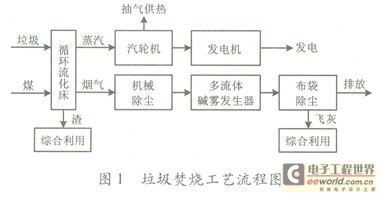
The waste incineration process is shown in Figure 1.

2.3 Process Overview
When the city garbage is transported to the incineration plant and poured into the garbage pool, it is lifted into the hopper and dropped into the furnace from the top of the incinerator, falling into the center of the moving bed; in the fluidized bed, the garbage is squeezed into pieces by the violently moving sand particles and burned quickly. The steam generated enters the steam turbine to do work and then generate electricity, and the flue gas generated enters the dust removal discharge or comprehensive utilization.
3. DCS control and management
The DCS control system should be based on perfect functions, risk dispersion, physical separation and load balancing to enhance the reliability and availability of the system. On this basis, the DCS system should adopt appropriate redundant configuration, consisting of distributed processing units, process input and output channels, data communication systems and human-machine interfaces, with self-diagnosis functions to the channel level and high reliability.
When any component in the system fails, the operation of the entire system should not be affected. In terms of control, the DCS system should complete the functions of the analog control system MCS (modulation control system), the sequential control system SCS (sequence control system), the electrical control system (electrical control system), the data acquisition system DAS (data acquisition system) and the boiler furnace safety monitoring system FSSS (furnaces safety supeoisory system) to meet the requirements of various operating conditions of the unit and ensure the safe, reliable and efficient operation of the unit; in terms of application, the DCS system should be easy to configure, use, modify and expand, open, and easy to communicate with other systems; in terms of specific object design, the DCS system should be designed in a hierarchical manner according to the production process of the garbage power plant, so that when there is a local fault in the DCS or a fault in the equipment, the lower level of control can be selected automatically or manually by the operator without losing control of the entire process.
4. System Implementation Introduction
The plant has a main control room that uses centralized furnace, machine and electricity control to monitor the following: 3x500 t/d circulating fluidized bed waste incinerators (rated steam production 75t/h), 2xC15MW condensing steam turbine generator sets and their auxiliary systems.
4.1 Host computer configuration
10 operator stations are used for real-time monitoring and management of the production site, including 1 shift supervisor station. Two engineer stations are set up for configuration and debugging, and also serve as trend alarm servers.
Lower computer configuration:
14 sets of I/O control stations complete on-site signal acquisition, engineering unit element conversion, control and interlocking control algorithms, control output, and transmit data and diagnostic results to the host computer through the system network. The specific configuration of the distributed processing unit (DPU) is as follows: 3 boilers, a total of 6 pairs (2 pairs per boiler, including 1 pair for the combustion system and 1 pair for steam and water); 2 steam turbines, a total of 4 pairs (2 pairs per steam turbine, including 1 pair for the main steam system, reheat steam system, heat recovery steam extraction system, and 1 pair for the oil system and vacuum system); 2 pairs for the public system (1 pair each for desuperheating and decompression, and deoxygenated feed water); 1 pair for remote circulating water; 1 pair for remote integrated water.
Distribution cabinet configuration:
The system is equipped with 3 sets of power distribution cabinets, namely 1 set in the boiler room, 1 set in the steam turbine room, and 1 set of instrument power cabinet.
The DCS power distribution cabinet and the instrument power distribution cabinet can receive two single-phase power supplies of 220V (1±10%) and (50±1)Hz provided by the power plant demand side. One of the two power supplies comes from the uninterruptible power supply UPS, and the other comes from the plant power supply. The instrument power distribution cabinet should be equipped with a two-way power supply automatic switching device.
Corresponding redundant power switching devices and circuit protection devices are configured in each cabinet and station, and these two power supplies are used to feed power in the cabinet.
Two sets of Weidmuller redundant DC power supplies are installed in each cabinet, and the two sets of redundant DC power supplies have sufficient capacity and appropriate voltage. Each DC power supply has a capacity that the load rate does not exceed 50% when running alone.
Any power failure should trigger an alarm, and the two redundant power supplies should be coupled through a diode switching circuit, that is, when one power supply fails, it will automatically switch to the other to ensure that the failure of any power supply will not cause power loss to any part of the system.
Each I/O cabinet is equipped with 2 sets of Weidmuller redundant DC power supplies from Germany, of which the 24V system power supply adopts a 1+1 redundant configuration scheme, and the SV system power supply adopts a 2+1 redundant configuration scheme.
Software version The software version used by the system is: win2000, SUPMAxsoo.
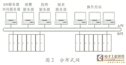
In a large system, the server can use distributed processing to reduce the load on a single machine. The above tasks can be completely undertaken by a single machine, or they can be distributed to two or more computers, as shown in Figure 2. In this way, the server's tasks are distributed to four computers, greatly reducing the load on a single machine and optimizing system performance.

4.2 Network Design Method
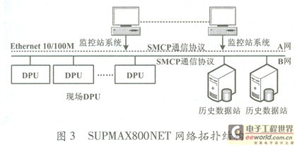
The SUPMAX800 system network is named SUPMAXSOONET network, which is a fully redundant 100 Mbit/s high-speed Ethernet network, consisting of two completely independent networks (network A and network B). The SUPMAxsooNET network is the backbone network of the SUPMAX800 system, connecting all workstations and DPUs. SUPMAX800NET complies with the international standard IEEE 802.3, with an adaptive rate of 10 Mhit·s-1/100 Mbit·s-1, adopts a star topology connection method, and uses active HUB or SWITCH as a repeater. SUPMAX800NET adopts the IP-based SMCP communication protocol independently developed by Shanghai Automation Instrument Co., Ltd., cancels the real-time server structure; and adopts a completely peer-to-peer method (i.e., point-to-point technology), reducing the risk of the entire network being paralyzed due to server crashes. The network topology is shown in Figure 3.

4.3 System Control Scheme
4.3.1 DAS system
The data acquisition system DAS uses the SUPMAX800 field control station to collect all I/O signal data, and provides operating parameters, input/output status, operation information, abnormal conditions and other data to operators in real time to guide them to operate safely and reliably. It also records and stores data for accident analysis signal processing.
4.3.2 MCS system
The SUPMAX800 system uses modular algorithm software and is reasonably configured to realize the control functions of each subsystem of the MCS. These subsystems include the feed water regulation system, main steam temperature regulation system, combustion control system, primary air volume control system, secondary air volume control system and material layer differential pressure control system.
①Water supply regulation system
The feedwater regulation system is a three-impulse full-range control system consisting of steam flow, drum water level and feedwater flow. Its task is to maintain the drum water level within the required range throughout the entire process from startup to full-load normal operation. At low load (such as below 25%), the feedwater regulation system maintains single-impulse control of the drum water level by adjusting the feedwater bypass regulating valve; at high load (such as above 28%), the drum water level is maintained by adjusting the feedwater main circuit regulating valve. The switching between low-load control and high-load control can be automatic or manual, and it is a disturbance-free two-way switching. During the design, the water level and steam flow are corrected by temperature and pressure compensation, and the feedwater flow is corrected by temperature compensation.
② Main steam temperature regulation The main steam temperature control system consists of two-stage temperature reduction regulation and adopts cascade regulation; the desuperheater outlet temperature is the lead-in temperature, the superheater outlet temperature is the main steam temperature, and is used as the main regulation parameter, and the load (main steam flow) is used as feedforward.
③ Combustion control boiler instruction (BD): Based on the comparison between the actual value of the steam main pipe pressure and the set value, the total boiler instruction is obtained through proportional integral differential (PID) operation, and then the instruction is distributed to each boiler (BD) in proportion, or distributed to each boiler (BD) in proportion according to the total load demand.
Heat signal (HR): The heat signal is the product of the differential of the drum pressure and the sum of the boiler heat storage coefficient and the steam flow rate.
The heat signal and the boiler command are passed through the high selection module to obtain an output signal. After fitting the corresponding air volume according to the boiler fuel-air characteristic curve, the total air volume command is obtained. The total air volume command minus the primary air volume command is the secondary air volume command SAFD.
Bed temperature control: Bed temperature is the main control object. The control strategy is to change the primary air volume when the load demand changes. The change in primary air volume directly causes the bed temperature to change, and the change in bed temperature causes the change in coal supply, thereby achieving bed temperature control and meeting the load demand.
④ Primary air volume control
Primary air volume control is used to ensure fluidization and according to load requirements.
⑤ Secondary air volume control
The secondary air volume instruction SAFD is corrected by the oxygen content and becomes the final secondary air volume instruction. After being compared with the actual secondary air, it is adjusted through PID calculation.
When the load demand remains unchanged, the primary air is not adjusted, and the bed temperature change is mainly met by adjusting the coal. If the amount of garbage is not controlled, manual operation is performed.
⑥ Material layer differential pressure control The material layer differential pressure is stabilized by slag discharge (slag cooler speed) (the wind chamber pressure is composed of the air distribution resistance and the material layer differential pressure, and the material layer differential pressure is obtained by subtracting the air chamber pressure from the air plate resistance and corresponds to the load demand).
4.3.3 Furnace Safety Monitoring System (FSSS)
The furnace safety monitoring system (FSSS) monitors the air supply system, induced draft system, furnace pressure and drum water level. Once a condition endangering the safety of the system is detected, the MFT (main fuel trip) action is immediately performed to cut off the main fuel, force the desuperheater down, and point out the cause of the first trip, give an audible and visual alarm signal, and perform related interlocking actions to ensure the safety of the boiler. When the following conditions occur, the combustion system stops.
① The MFT protection logic is configured by the DCS system, and the triggering conditions are: manual MFT, induced draft fan tripping, primary fan tripping, two return fan tripping, furnace pressure high, wind chamber air pressure high, wind chamber air pressure too low, drum water level high, drum water level low, bed temperature continuously high, bed temperature continuously low, primary air volume low.
②MFT reset: reset after furnace purging under different starting conditions of hot and cold states.
Previous article:Research on the application of CAN bus technology in the control system of industrial palletizing robots
Next article:DCS control system
- Popular Resources
- Popular amplifiers
- Molex leverages SAP solutions to drive smart supply chain collaboration
- Pickering Launches New Future-Proof PXIe Single-Slot Controller for High-Performance Test and Measurement Applications
- CGD and Qorvo to jointly revolutionize motor control solutions
- Advanced gameplay, Harting takes your PCB board connection to a new level!
- Nidec Intelligent Motion is the first to launch an electric clutch ECU for two-wheeled vehicles
- Bosch and Tsinghua University renew cooperation agreement on artificial intelligence research to jointly promote the development of artificial intelligence in the industrial field
- GigaDevice unveils new MCU products, deeply unlocking industrial application scenarios with diversified products and solutions
- Advantech: Investing in Edge AI Innovation to Drive an Intelligent Future
- CGD and QORVO will revolutionize motor control solutions
- Innolux's intelligent steer-by-wire solution makes cars smarter and safer
- 8051 MCU - Parity Check
- How to efficiently balance the sensitivity of tactile sensing interfaces
- What should I do if the servo motor shakes? What causes the servo motor to shake quickly?
- 【Brushless Motor】Analysis of three-phase BLDC motor and sharing of two popular development boards
- Midea Industrial Technology's subsidiaries Clou Electronics and Hekang New Energy jointly appeared at the Munich Battery Energy Storage Exhibition and Solar Energy Exhibition
- Guoxin Sichen | Application of ferroelectric memory PB85RS2MC in power battery management, with a capacity of 2M
- Analysis of common faults of frequency converter
- In a head-on competition with Qualcomm, what kind of cockpit products has Intel come up with?
- Dalian Rongke's all-vanadium liquid flow battery energy storage equipment industrialization project has entered the sprint stage before production
- Allegro MicroSystems Introduces Advanced Magnetic and Inductive Position Sensing Solutions at Electronica 2024
- Car key in the left hand, liveness detection radar in the right hand, UWB is imperative for cars!
- After a decade of rapid development, domestic CIS has entered the market
- Aegis Dagger Battery + Thor EM-i Super Hybrid, Geely New Energy has thrown out two "king bombs"
- A brief discussion on functional safety - fault, error, and failure
- In the smart car 2.0 cycle, these core industry chains are facing major opportunities!
- The United States and Japan are developing new batteries. CATL faces challenges? How should China's new energy battery industry respond?
- Murata launches high-precision 6-axis inertial sensor for automobiles
- Ford patents pre-charge alarm to help save costs and respond to emergencies
- New real-time microcontroller system from Texas Instruments enables smarter processing in automotive and industrial applications
- How to make a jumper between the pads of two different plug-ins in PCB?
- How to complete a waveform analyzer based on 51 single chip microcomputer
- "Core" ecosystem, "Assist" security, "Connect" the future. Registration for the 2021 STM32 China Summit and Fan Carnival is now open!
- Critical issues with naked code
- Please tell me the role of these two resistors in the circuit
- Is the naked-eye 3D large screen also made of light-emitting diodes (LED)? What is the principle?
- Comparison of TI's tms320 series DSP
- Playing with Zynq Serial 45——[ex64] Image Laplace Sharpening Processing of MT9V034 Camera
- New employee: I am the most idle person in the company, so my boss assigned me to write the bootloader
- Mobile Phone RF Design Skills

 JM38510/11405BGC


 京公网安备 11010802033920号