Passive filters use the characteristics of capacitor and inductor resonance to suppress high-order harmonic components of specific frequencies and improve power factor. However, their large size, fixed filter frequency, and series/parallel resonance limit their widespread use [1]. In the past decade, active power filters (APFs) have attracted widespread attention for their ability to compensate for harmonics, suppress flicker, compensate for reactive power, and have multiple functions. This new type of harmonic suppression device has broad development and application prospects. Compared with passive filters, APFs can achieve dynamic compensation and have the advantages of being small in size and not prone to resonance [2].
In order to ensure the working performance of the active power filter, it is crucial to detect the harmonic components in the load in real time and accurately and obtain the correct harmonic compensation signal. At present, the main methods for harmonic current detection include methods based on instantaneous reactive power theory, fast Fourier transform (FFT) based on frequency domain analysis, and adaptive [3,4], but these methods involve many parameters, large amount of calculation, and complex process, especially for the delay problem of APF system. In view of the inherent delay characteristics of the internal structure of the digital APF system, the GM (1,1) gray prediction model of the gray system theory is used to propose an APF prediction control scheme based on gray prediction.
2. System Implementation
2.1 Working principle and mathematical model of APF system
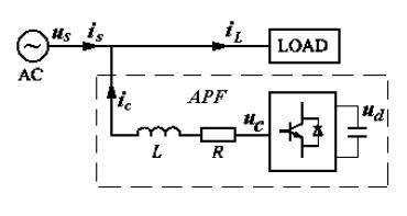
The schematic diagram of the parallel active filter circuit is shown in Figure 1, where us and uc are the grid power phase voltage and the inverter output phase voltage respectively, L is the choke inductor, and R is the inductor internal resistance and the equivalent resistance of the line. Assuming the three-phase balance of the system, the system can be approximately described by a single phase. The current Li and the compensation current ci output by the APF can be obtained from Figure 1. The mathematical model of the APF.
Figure 1 APF main circuit block diagram
In APF, when quickly tracking the changes in harmonic current in the load in real time, the harmonic current and compensation current of the load are usually detected at the current moment, and the compensation amount of the inverter at the next moment is calculated, which brings a delay of at least one sampling cycle to the system. In addition, the system is affected by the sampling of voltage and current, the phase lag of the input filter, and the operation time required for parameter calculation, which will also bring time lag to the control of the system. The control delay will directly affect the performance and stability of the system.
Assuming that the system signal input filter is an ideal link, it does not bring phase lag to the harmonic components within the compensation range. By selecting high A/D converters and data processors, the system data processing and control signal generation are completed within one switching cycle of the power switch device. That is, the discrete control system is constructed, from signal sampling to forming PWM voltage instructions, and generating pulse width modulation signals in the next switching cycle to be output by the inverter, which means that the minimum delay is about one switching cycle. The structural diagram of the system current loop can be written as
Figure 2 System structure diagram
Among them, Gn (s), K, e-sT are the transfer functions of the harmonic detection link, inverter, current proportional regulator, and delay link respectively. Among them, the average value of the output voltage uc of the PWM inverter in one sampling period is uc.
2.2 Implementation of grey prediction control system based on APF
Figure 3 is a block diagram of the APF grey prediction control system. The system collects and organizes the load current and APF output compensation current at time k through a sampling device. The grey prediction device is used to build a model to obtain the load harmonic current at time k+1. The APF output current value iˆc (k + 1) at time k+1 is predicted based on the APF model, control quantity and ic (k). The control quantity is determined to make the future output ic as close to the target as possible.

Click to see the original image
Fig.3 Structure diagram of grey prediction control system
2.2.1 Prediction of load harmonic current
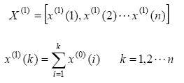
In order to continuously take into account the newly acquired data, it is required to send each newly acquired data into the original sequence X (0), rebuild GM (1,1), and re-predict. We call it the new information model. With this new information model, as time goes by, the new information becomes more and more, the storage capacity continues to expand, and the amount of calculation also continues to increase. This is not suitable for the real-time and rapid requirements of industrial process control, and the information significance of the old data will decrease over time, and even drown out the new information. In order to overcome this contradiction, here, every time a new information is added, an old information is removed, so that the number of original sequence data n remains unchanged during rolling modeling.
The predicted value of the system harmonic current at time (k+1) can be obtained
2.2.2 Prediction of APF compensation current
The corresponding discrete equation can be approximately described as:
Where T is the system sampling period, then the predicted value of the APF compensation current at time k+1 can be obtained:
Take
, then the above formula can be rewritten as


2.2.3 Design of control law
Take the objective function
Then the optimal control law of the system can be obtained
3. System simulation
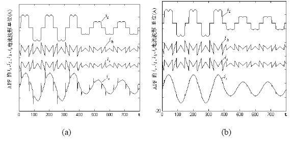
The nonlinear load of the system adopts a three-phase uncontrolled rectifier circuit, and the nonlinear load current and harmonic current waveforms of the system are shown in Figure 6. The sampling frequency of the system is fs = 10kHz, L = 1mH, R = 0.5Ω, Kp = Kq = 1, the number of sequence group elements in the calculation process n = 5, and GM (1, 1) is used to predict the harmonic signal of the system. The simulation results of the system are shown in Figure 4:
Figure 4 Load current waveform of the power grid after APF compensation
The current waveforms of each part of the system after the control of the system in Figure 2 and Figure 3 are shown in Figure 4 (a) and (b) respectively. Comparing Figure 4 (a) and (b), it can be seen that the use of grey prediction control can better overcome the influence of APF lag on harmonic compensation and improve the performance of the system.
4. Conclusion
This study achieved the following innovations:
(1) An APF predictive control scheme based on grey prediction is proposed;
(2) The GM(1,1) prediction model of load harmonic current is established by applying the grey system theory. The harmonic current iˆh (k + 1) of the k+1 step is predicted in the kth step. On this basis, the compensation component is used to achieve zero-beat tracking of the load harmonic component.
(3) The grey system was implemented, and the prediction of load harmonic current, prediction of APF compensation current and design of control law were completed.
This study draws the following conclusions:
(1) At present, the main methods for harmonic current detection include methods based on instantaneous reactive power theory, fast Fourier transform (FFT) based on frequency domain analysis, and adaptive [3,4] methods. However, these methods involve many parameters, large amount of calculation, and complex process, especially for APF systems, there is a delay problem.
(2) Grey prediction requires less raw data, less calculation and simpler method.
(3) A control method for active power filters based on the grey system model uses grey system theory to predict load harmonics and applies it to active filters to improve the dynamic compensation performance of active filters.
(4) The use of grey prediction control can better overcome the impact of APF lag on harmonic compensation and improve the performance of the system.
Previous article:Introduction to the Principle of Optical Touch Screen and Its Market Analysis
Next article:Using Buck Controllers in Buck-Boost Power Supply Designs
- Popular Resources
- Popular amplifiers
- Molex leverages SAP solutions to drive smart supply chain collaboration
- Pickering Launches New Future-Proof PXIe Single-Slot Controller for High-Performance Test and Measurement Applications
- CGD and Qorvo to jointly revolutionize motor control solutions
- Advanced gameplay, Harting takes your PCB board connection to a new level!
- Nidec Intelligent Motion is the first to launch an electric clutch ECU for two-wheeled vehicles
- Bosch and Tsinghua University renew cooperation agreement on artificial intelligence research to jointly promote the development of artificial intelligence in the industrial field
- GigaDevice unveils new MCU products, deeply unlocking industrial application scenarios with diversified products and solutions
- Advantech: Investing in Edge AI Innovation to Drive an Intelligent Future
- CGD and QORVO will revolutionize motor control solutions
- Innolux's intelligent steer-by-wire solution makes cars smarter and safer
- 8051 MCU - Parity Check
- How to efficiently balance the sensitivity of tactile sensing interfaces
- What should I do if the servo motor shakes? What causes the servo motor to shake quickly?
- 【Brushless Motor】Analysis of three-phase BLDC motor and sharing of two popular development boards
- Midea Industrial Technology's subsidiaries Clou Electronics and Hekang New Energy jointly appeared at the Munich Battery Energy Storage Exhibition and Solar Energy Exhibition
- Guoxin Sichen | Application of ferroelectric memory PB85RS2MC in power battery management, with a capacity of 2M
- Analysis of common faults of frequency converter
- In a head-on competition with Qualcomm, what kind of cockpit products has Intel come up with?
- Dalian Rongke's all-vanadium liquid flow battery energy storage equipment industrialization project has entered the sprint stage before production
- Allegro MicroSystems Introduces Advanced Magnetic and Inductive Position Sensing Solutions at Electronica 2024
- Car key in the left hand, liveness detection radar in the right hand, UWB is imperative for cars!
- After a decade of rapid development, domestic CIS has entered the market
- Aegis Dagger Battery + Thor EM-i Super Hybrid, Geely New Energy has thrown out two "king bombs"
- A brief discussion on functional safety - fault, error, and failure
- In the smart car 2.0 cycle, these core industry chains are facing major opportunities!
- The United States and Japan are developing new batteries. CATL faces challenges? How should China's new energy battery industry respond?
- Murata launches high-precision 6-axis inertial sensor for automobiles
- Ford patents pre-charge alarm to help save costs and respond to emergencies
- New real-time microcontroller system from Texas Instruments enables smarter processing in automotive and industrial applications
- Today at 10:00 am, Keysight Technologies' award-winning live broadcast begins | Evolution and updates of signal integrity testing
- Proteus simulation implementation of simple single-chip calculator
- 【GD32L233C-START Review】 Second Development Board Function Review
- Technologies such as RFID enhance the security of smart IoT
- I2C Pressure Sensor
- Differences between CPU and CLA in C28x+FPU architecture and error handling techniques
- The drilling marks are clear, why is there a hole missing on the PCB?
- Prize-winning quiz | TE "New Energy Application Solutions White Paper"
- Why are XH connector manufacturers so stupid?
- A summary of the most downloaded electronic technical materials this week (2020.6.1~5)


 MAX4336EXT+


 京公网安备 11010802033920号