At the forefront of innovation in power design, Vicor has pioneered a power component design methodology that enables engineers to predictably and cost-effectively configure high-performance power systems using industry-proven components using a proven methodology.
Power components are dedicated modules that have been fully optimized by professional power engineers for efficiency, power density, transient response and EMI. With this approach, instead of developing a power chain using discrete components, all of these key parameters have been optimized and designers are ready with a most suitable solution for any power design project. In addition, the structure of these modules is fully suitable for reuse in future designs, saving time and effort.
When combined with the array of tools and resources available, this approach will enable a faster and simpler design cycle with less risk to complete projects and bring products to market.
The power component design methodology has three steps: identify, build and implement.
Step 1 – Identify
This is a "big picture" view of the power requirements for a project, defining the number of rails, voltage and current requirements, while taking into account the timeline of the project. At this stage, a list of these requirements is made and initial consideration is given to the types of products that can be used to meet them.
What products will meet the requirements? There are many sources of this information. For example, Vicor offers a solution selector tool that searches a database of available components and recommends solutions that meet the customer's input and output requirements. With an intelligent tool such as the Vicor solution selector, the time required to generate a shortlist of possible components can be reduced to almost zero, and the best component for a particular design can be easily selected based on the application. Most engineers simply do not have the luxury of "learning time" to complete this important task manually.
What are the typical power components available?
First up is power delivery. Here, power components must take high voltage DC or AC power and convert it to a safety extra low voltage ( SELV ). In many high-performance applications, engineers are using high voltage and high current to deliver power to their systems. Because of the heat dissipation from the device, choosing thermally adaptable components is critical. These components will need to be placed in multiple locations within the system. This includes power systems mounted in a chassis or motherboard, and cooling of each component needs to be considered.
Next comes the delivery of power from the SELV to the point of load. Engineers need to carefully select the appropriate voltage rail for their application. Too many conversion stages will reduce the efficiency of the application. In recent years, power supply designs have begun to move from 12V rails to 48V rails that provide higher system efficiency. The challenge is to select the best components that can provide the right performance at the highest efficiency. Tools like Vicor's Whiteboard can help engineers evaluate the performance of their designs using different SELVs .
Finally, there is the choice of point-of-load components. Based on the SELV selected, engineers need to select the components needed to achieve the PoL requirements so that less than 1V can be achieved at high currents. Isolation and regulation are required, and DC-DC converters such as VicorDC Converter Modules (DCMs) can be used. Designers can also use components designed for Factorized Power Architecture (FPA), where the regulation and voltage conversion/isolation functions are separated. Choosing the latter helps designers achieve high power density, which is equivalent to having the ability to convert a large amount of power in a small space.
Step 2 - Build
The first step in building a system is to create a block diagram of the power system, starting at the output and working backward toward the input. It works best to start at the lowest power level and work from there so that the power component classes can be reviewed and changes made if necessary as power levels increase.
It is important to choose the right component category for the appropriate power level. For example, at low power, a system-in-package (SiP) product such as the Vicor ZVS buck regulator is the best solution. At higher power levels, a better approach may be to use Vicor's ChiP products (Converter housed in Package). Depending on the complexity of the number of voltage rails required to drive the load, a combination of SiP and ChiP can be used in the application.
This will help achieve maximum power density and cost-effectiveness within the system and keep every device in the system operating at high efficiency.
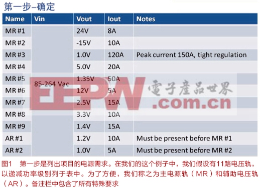
Looking back at Figure 1, it is clear that the first three rails (MR#1, 2, and 3) are the rails that require the highest power level devices, while the last five rails (MR#7 through AR#2) are the lowest power level devices. The rest (MR#4 through MR#6) are somewhere in between. This is where the designer will need to use their judgment to make device choices. Once the outputs are done, we can start to build a picture of the power modules and power levels we need in the system block diagram category.
Reference address of this article: http://www.eepw.com.cn/article/266047.htm
Step 3 - Implementation
Once the modules are complete, designers need to match part numbers to these modules while taking care to implement all the dedicated circuitry for functionality and emulation of the respective power conversion component chains. Other circuits that need to be developed may include filters, hold-up circuits, and power sequencing. At this stage of the design, engineers should also consider thermal, termination, and packaging considerations.
In our case, there are some special requirements for the power supply: there is a delay on MR#3 before the auxiliary voltage rail rises, and tight regulation of MR#3 will require the use of a remote sense loop. It also makes sense to consider configuring a PRM (Pre-regulator Module) to achieve accurate load current limit and other parameters that accurately match the voltage rail and load requirements.
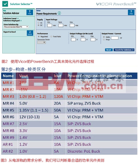
For engineers who need to use PRM to tune their designs, Vicor offers a PowerBench simulation tool that can help further understand the performance of the system.
Design and Development Tools
In the past, engineers made component selections and analyzed power system efficiency (and overall system performance) at each stage by referring to calculations in device datasheets .
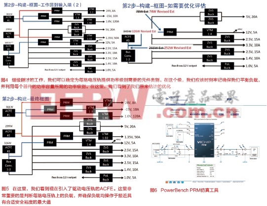
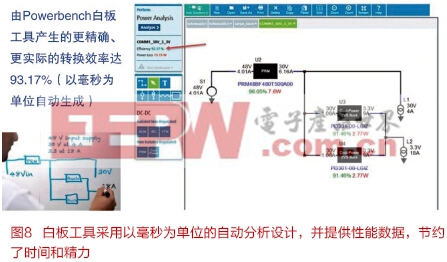
While completely satisfying, this approach can become a bit tedious. To simplify the design process and save time, Vicor recently launched the PowerBench whiteboard tool. The whiteboard tool is an online tool for designing and analyzing power systems using a suitable set of Vicor power conversion components. Instead of having to look up the operating and efficiency parameters contained in the data sheet, the engineer can simply draw a circuit block diagram using the online tool, and all calculations can be completed in a few milliseconds.
By retaining the system's familiar sketch symbols and adding automatic parameter lookup and calculation, the Whiteboard Tool can further reduce the time to complete a design using the Power Component Design Methodology.
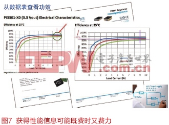
In addition, Vicor 's solution selection tool can be tightly integrated with the whiteboard tool. Therefore, the design recommended by the solution selection tool can automatically import the design into the whiteboard tool so that engineers do not need to draw the system themselves. At this point, engineers can adjust the design to further meet their needs and quickly understand the efficiency of the design.
in conclusion
Power components have become a key factor in helping engineers design complex, high-performance power systems for today's electronic systems . Because power design experts have optimized efficiency, power density, transient response, EMI, and cost-effectiveness, almost any electronic engineer can use these devices to develop a power system to meet challenging high-performance requirements.
Driven by the need for better thermal performance, there have been many recent innovations in power components . The ChiP platform provides a solution for strong thermal dissipation using double-sided cooling and is a good example of board-mounted power. In the future, other innovations will further simplify the tasks of power system designers, especially on the front end of the power supply. The Power Device Design Methodology provides a simple three-step approach that enables engineers, even if they are not power experts, to build complex power chains that can provide high efficiency and high power density. This approach is further simplified through the use of online tools. However, unlike many design solutions, the Power Component Design Methodology eliminates the pain and risk from the design process without requiring engineers to spend time learning the technology. Engineers can use this method without special training, shortening development time while ensuring that their next power chain is optimized to provide the required performance.
Previous article:Power supply tips: A small oversight can ruin EMI performance
Next article:Single-phase sine wave inverter power supply
- MathWorks and NXP Collaborate to Launch Model-Based Design Toolbox for Battery Management Systems
- STMicroelectronics' advanced galvanically isolated gate driver STGAP3S provides flexible protection for IGBTs and SiC MOSFETs
- New diaphragm-free solid-state lithium battery technology is launched: the distance between the positive and negative electrodes is less than 0.000001 meters
- [“Source” Observe the Autumn Series] Application and testing of the next generation of semiconductor gallium oxide device photodetectors
- 采用自主设计封装,绝缘电阻显著提高!ROHM开发出更高电压xEV系统的SiC肖特基势垒二极管
- Will GaN replace SiC? PI's disruptive 1700V InnoMux2 is here to demonstrate
- From Isolation to the Third and a Half Generation: Understanding Naxinwei's Gate Driver IC in One Article
- The appeal of 48 V technology: importance, benefits and key factors in system-level applications
- Important breakthrough in recycling of used lithium-ion batteries
- LED chemical incompatibility test to see which chemicals LEDs can be used with
- Application of ARM9 hardware coprocessor on WinCE embedded motherboard
- What are the key points for selecting rotor flowmeter?
- LM317 high power charger circuit
- A brief analysis of Embest's application and development of embedded medical devices
- Single-phase RC protection circuit
- stm32 PVD programmable voltage monitor
- Introduction and measurement of edge trigger and level trigger of 51 single chip microcomputer
- Improved design of Linux system software shell protection technology
- What to do if the ABB robot protection device stops
- Allegro MicroSystems Introduces Advanced Magnetic and Inductive Position Sensing Solutions at Electronica 2024
- Car key in the left hand, liveness detection radar in the right hand, UWB is imperative for cars!
- After a decade of rapid development, domestic CIS has entered the market
- Aegis Dagger Battery + Thor EM-i Super Hybrid, Geely New Energy has thrown out two "king bombs"
- A brief discussion on functional safety - fault, error, and failure
- In the smart car 2.0 cycle, these core industry chains are facing major opportunities!
- The United States and Japan are developing new batteries. CATL faces challenges? How should China's new energy battery industry respond?
- Murata launches high-precision 6-axis inertial sensor for automobiles
- Ford patents pre-charge alarm to help save costs and respond to emergencies
- New real-time microcontroller system from Texas Instruments enables smarter processing in automotive and industrial applications
- TI document: How to program a DSP
- Live broadcast with prizes | Registration is open for TI chip technology to help motor development!
- 80-bit extended precision floating point in OCaml
- Tutorial: How to use Vivado HLS to accelerate algorithm development on FPGA
- [Contactless facial recognition access control system] + 1-MAIX_BIT development environment construction
- 【Project source code】Data on FPGA-based DDR3
- A collection of selected C language resources - from basic theory to embedded development practice
- Why was DP1332E suddenly chosen as the PN532 replacement compatible chip?
- How is the brightness of LCD segment code screen defined?
- WeChat applet and RSL10 Bluetooth two-way communication

 Automated Guided Vehicles: Optimal Path Planning Methods and Models
 CVPR 2023 Paper Summary: Adversarial Attack and Defense


 京公网安备 11010802033920号