Internal structure and function of TL431
1. Symbol of TL431
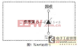
The symbol of the device is shown in Figure 1. The three pins are: cathode (CATHODE), anode (ANODE) and reference terminal (REF), and the reference voltage is 2.5V.
2. Internal circuit diagram of TL431
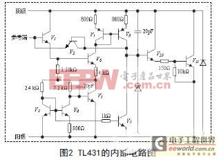
As can be seen from the internal circuit diagram Figure 2, it consists of a multi-pole amplifier circuit, a bias circuit, a compensation and protection circuit, in which transistor V1 constitutes the input pole, V3, V4, and V5 constitute the voltage reference, the mirror constant current source composed of V7 and V8 and V6 and V9 constitute a differential amplifier as an intermediate stage, V10 and V11 form a composite tube to constitute the output, and some other resistors, capacitors, and diodes play the role of bias, compensation, and protection respectively. In principle, it is a single-ended input and single-ended output DC amplifier.
However, its equivalent functional diagram is shown in Figure 3, which consists of a 2.5V precision reference voltage source, a voltage comparator and an output switch tube. The output voltage of the reference terminal is compared with the precision reference voltage source Vref. When the reference terminal voltage exceeds 2.5V, TL431 is turned on immediately. Because the R terminal control voltage error is ±1%, the reference terminal can accurately control the conduction and cutoff of TL431.

Parallel voltage regulator circuit design
1. Basic parallel voltage regulation circuit principle
TL431 contains a 2.5V reference voltage inside, so when output feedback is introduced at the Vref end, the device can control the output voltage through a wide range of shunting from the cathode to the anode. As shown in the circuit in Figure 4, when the resistance values of R1 and R2 are determined, the two introduce feedback to the voltage division of VO. If it increases, the feedback amount increases, and the shunting of TL431 also increases, which in turn causes VO to drop. Obviously, this deep negative feedback circuit must be stable at a reference voltage, at which time VO=(1+R1/R2)Vref. By selecting different values of R1 and R2, any voltage output in the range of 2.5V to 36V can be obtained. In particular, when R1=R2, VO=5V. If R1 is short-circuited and R2 is open-circuited, that is, the reference end is short-circuited with the cathode end, then the output voltage VO=2.5V (reference end voltage) is obtained, which is most suitable for use as a reference voltage source in digital voltmeters and analog-to-digital converters or other circuits.
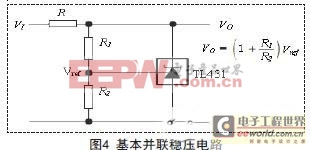
It should be noted that the necessary conditions for the operation of TL431 must be met when selecting the resistor R , that is, the current through the cathode must be greater than 1mA, and R1 and R2 must be selected with the same type of resistors with an accuracy of 1% to ensure the long-term stability of the reference power supply.
2. Parallel current expansion and voltage stabilization circuit
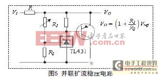
In many application circuits, FIG5 is actually a circuit slightly improved on the basis of FIG4, using transistors to expand the current to form a large current reference voltage source, and the transistors in FIG5 can be selected with transistors of different powers according to the size of the load current. At this time, the power of the current limiting resistor R should also be increased accordingly.
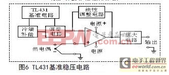
The parallel voltage regulator circuit is suitable for various sensors, transmitters, and various A/D converters of instruments. Figure 6 shows its application in the thermocouple transmitter.
 Series current expansion voltage stabilization circuit
In addition to being used in parallel voltage regulation circuits, the power consumption of the current limiting resistor R in Figures 4 and 5 will change with the input voltage. A high-power current limiting resistor is required, otherwise it will be damaged due to excessive current .
The above problem is solved by adopting the connection method of series connection, as shown in Figure 7. A part of the current flowing through the current limiting resistor R is shunted to two NPN transistors V1 and V2, and the NPN type Darlington tube is formed through the same polarity connection of NPN+NPN. The amplification factor is the product of the amplification factors of V1 and V2. In this way, the collector not only shunts most of the current borne by the resistor R in Figure 5, solving the problem of the required high-power resistor, but also because the current amplification ability of the Darlington tube is enhanced, the load capacity of TL431 is enhanced, and a high-current load can be connected without a high-power transistor.
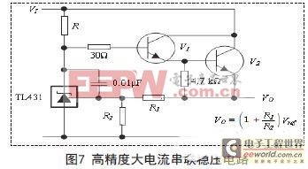
In practical applications, when the load current is 50mA, the current flowing through R is only 1mA, and the current flowing through the Darlington collector is 49mA. The resistor R can be a small-power surface mount resistor to meet the needs and realize the constant voltage function. Moreover, under wide power input, the output change is small. As shown in Table 1, the test conditions are R1=2.5KΩ, R2=3.5KΩ, R=3KΩ, the load current is 50mA, TL431 uses SOT-89 package, model TL431QPK, and only changes 1mV under wide voltage power supply. If used in a parallel circuit, it can replace the circuit shown in Figure 5 for better results.
The circuit shown in Figure 6 has good thermal stability. Since the temperature drift of TL431 is low, 6mV from 0℃ to 40℃, 14mV from -40℃ to 85℃ and -40℃ to 125℃, the temperature characteristics of the output voltage are much better than those of ordinary constant voltage sources. If R1 and R2 use resistors with low temperature drift coefficients, the overall temperature drift of the constant voltage circuit is also very small, and no additional temperature compensation circuit is required in the application. In actual applications, R1=2.5KΩ, R2=3.5KΩ, 3 chips are randomly selected from 50 chips of model TL431QPK, SOT-89 package, and the circuit shown in Figure 6 is used as the voltage stabilization circuit of the differential transformer displacement sensor. The temperature range is -40℃~125℃. The temperature drift measurement is shown in Table 2, with only a few to more than ten millivolts, which meets the given indicators.
It can be seen that the series circuit improves the stability accuracy, reduces the power consumption of TL431, and reduces the probability of TL431 being damaged due to overheating. The above circuit can not only be used as an industrial-grade sensor voltage stabilization reference, but also can be a precision voltage stabilization power supply reference for military-grade products with a wide temperature range and low temperature drift. It is a practical precision linear voltage stabilization circuit.
Conclusion
Based on the internal structure and characteristics of the TL431 three-terminal adjustable precision, this paper describes the basic composition and performance of the parallel voltage regulator circuit and the series voltage regulator circuit. A design scheme for a linear precision voltage regulator of TL431 is proposed . After a large number of experiments and long-term applications, it is proved that the adjustable precision
voltage has achieved the functions of high power, wide voltage, and low temperature drift, with high cost performance and strong performance.
Previous article:Analysis of the causes of electromagnetic radiation interference generated by switching regulated power supplies
Next article:Technology: Engineers share the design of series-adjusted voltage-stabilized power supply circuit
Recommended ReadingLatest update time:2024-11-22 14:19

- RAQ #223: How to measure and determine soft-start timing without a soft-start equation?
- Vicor high-performance power modules enable the development of low-altitude avionics and EVTOL
- Bourns Launches Two Thick Film Resistor Series with High Power Dissipation Capabilities in Compact TO-220 and DPAK Package Designs
- Bourns Launches New High-Pulse Brake Resistor Series with Superior Energy Dissipation Capabilities
- Nexperia launches new 120 V/4 A half-bridge gate driver to further improve robustness and efficiency in industrial and automotive applications
- Vishay's New 150 V MOSFETs Offer Industry-Leading Power Loss Performance
- The first generation of SGT MOSFET series from Qiangmao: innovative trench technology, automotive-grade 60 VN channel, breakthrough in high-efficiency performance of automotive electronics
- DC/DC Power Supplies for Automotive Applications
- MathWorks and NXP Collaborate to Launch Model-Based Design Toolbox for Battery Management Systems
- Intel promotes AI with multi-dimensional efforts in technology, application, and ecology
- ChinaJoy Qualcomm Snapdragon Theme Pavilion takes you to experience the new changes in digital entertainment in the 5G era
- Infineon's latest generation IGBT technology platform enables precise control of speed and position
- Two test methods for LED lighting life
- Don't Let Lightning Induced Surges Scare You
- Application of brushless motor controller ML4425/4426
- Easy identification of LED power supply quality
- World's first integrated photovoltaic solar system completed in Israel
- Sliding window mean filter for avr microcontroller AD conversion
- What does call mean in the detailed explanation of ABB robot programming instructions?
- RAQ #223: How to measure and determine soft-start timing without a soft-start equation?
- RAQ #223: How to measure and determine soft-start timing without a soft-start equation?
- GigaDevice's full range of automotive-grade SPI NOR Flash GD25/55 wins ISO 26262 ASIL D functional safety certification
- GigaDevice's full range of automotive-grade SPI NOR Flash GD25/55 wins ISO 26262 ASIL D functional safety certification
- New IsoVu™ Isolated Current Probes: Bringing a New Dimension to Current Measurements
- New IsoVu™ Isolated Current Probes: Bringing a New Dimension to Current Measurements
- Infineon Technologies Launches ModusToolbox™ Motor Kit to Simplify Motor Control Development
- Infineon Technologies Launches ModusToolbox™ Motor Kit to Simplify Motor Control Development
- STMicroelectronics IO-Link Actuator Board Brings Turnkey Reference Design to Industrial Monitoring and Equipment Manufacturers
- Melexis uses coreless technology to reduce the size of current sensing devices
- [Domestic RISC-V Linux Board Fang·Starlight VisionFive Trial Report] Successfully communicated with DWIN screen
- Application of CAE in Automobile Development
- Looking for unboxing test of AWR1642BOOST
- What happens when a low-speed AD collects a high-frequency signal? (Those who have tried it or done a circuit experiment are welcome to come in!)
- 【RT-Thread Reading Notes】Chapter 7-10 Reading Notes
- The funniest sentence in the forum in 2005!!
- Xunwei-IMX6ULL-QT application_porting ssh on the development board
- msp430 writes ADS1115
- 【TI recommended course】# Master the design of flyback power transformer and circuit#
- MicroPython Hands-on (33) - Weather Forecast for the Internet of Things

 Monocular semantic map localization for autonomous vehicles


 京公网安备 11010802033920号