Today's LED lighting has a variety of applications, from simple incandescent or cold cathode fluorescent lamp (CCFL) replacements to new architectural, industrial, medical and other applications. In order to optimize the matching of lamps and light in the application, different LED lighting applications usually have corresponding performance standard requirements.
To drive LEDs, engineers can choose from a wide variety of driver architectures, but each architecture has its own advantages and disadvantages, and its adaptability to specific applications varies. There are many factors to consider when choosing a driver architecture, among which cost occupies the first position, followed by isolation, dimming, flicker, color temperature, power factor, reliability, thermal management and other issues.
There are several basic LED driver architectures: secondary side control, primary side control, isolated/non-isolated. In addition, power factor control (PFC) is also a major performance consideration in many applications, and its solutions consist of two-stage or single-stage drivers with PFC function, or single-stage drivers without PFC function (mainly used in applications with power less than 5W). Therefore, the entire driver subsystem is the result of a series of trade-offs, with the aim of reducing the bill of materials (BOM) cost and achieving the highest efficiency while providing dimming functions and creating a temperature-controlled and fault-protected product.
Basic drive architecture
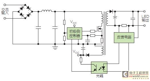
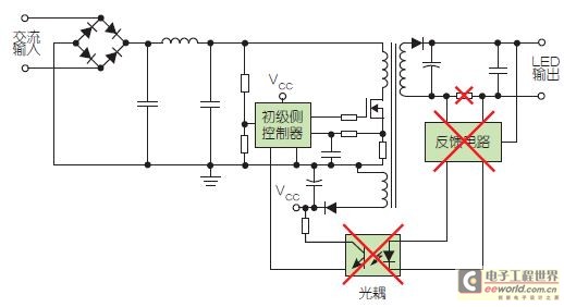
To achieve optimal isolation and control, the secondary-side control architecture monitors the output voltage/current and provides feedback signals to the primary-side driver through an optically isolated path (Figure 1). This feedback signal enables the secondary-side controller to provide better current and voltage control accuracy. Simpler primary-side control schemes eliminate the secondary-side controller and the optically isolated signal path, thereby reducing system cost and size while improving system performance. In this scheme, the primary-side driver determines the output current and voltage through primary-side waveform analysis (Figure 1). Depending on the quality of the analysis, primary-side control can match or even exceed secondary-side regulation and performance, making it a common solution for today's isolated LED drivers.


Figure 1: Two common LED driver schemes use secondary-side control (top) and primary-side control (bottom). Secondary-side control provides better current and voltage control accuracy, but primary-side control reduces component count and system size while improving performance.
The basic primary-side control circuit achieves isolation through the output stage transformer. However, to reduce component cost, non-isolated solutions use an inductor instead of a transformer and can use a buck controller instead of a primary-side driver flyback circuit (Figure 2). In non-isolated solutions, the control mechanism is simplified, but the circuit requires more complex physical isolation to prevent short circuits between the input and output. Currently, most LED driver designs use an isolated architecture. In the next year or two, advances in circuit design will provide solutions to further reduce costs.

Figure 2: The primary-side driver can be designed in an isolated configuration by using a transformer in the output stage, or in a nonisolated configuration by replacing the output transformer with an inductor and selecting a buck controller instead of the flyback circuit.
Power Factor Basics
When the input voltage and current are in phase and the input voltage and current waveforms are consistent, the power factor is ideally "1". When the phase difference between the input voltage and input current waveforms increases, the power factor will decrease and the system efficiency will also decrease. However, the boost converter has a built-in current waveform control function that can track the input voltage waveform to maintain a power factor close to 1.
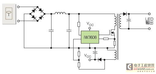
To improve the power factor, a two-stage power factor correction (PFC) boost circuit can be added before the primary-side driver circuit and control circuit (Figure 3). The PFC circuit also eliminates the flicker problem caused by 2 times the line frequency. In the example, a flyback converter is used in the output stage to provide isolation for the iW3616 driver circuit. The primary-side sensing technology used in this driver chip achieves excellent line voltage and LED load current regulation without the use of secondary-side feedback circuits, while eliminating the opto-isolator feedback loop. In addition, the iW3616's real-time cycle waveform analysis technology also improves the setting response speed of the dimmer. The digital control loop can also maintain the overall operating conditions stable without the need for loop compensation devices.

Figure 3: By adding a two-stage power factor correction boost circuit to the iW3616 digital power controller, the driver circuit can achieve flicker-free dimming and very high power factor (>0.95).
PFC can also be implemented in a single-stage primary-side drive and control circuit. In such a system, the driver controls the input current waveform by modulating the input impedance, thereby regulating the power factor.
The two-stage PFC architecture achieves near-perfect PFC while effectively eliminating output ripple, thus significantly improving the flicker problem in LED lamps. However, the two-stage boost circuit requires more components, so the implementation cost is also higher. In contrast, although the single-stage driver with PFC function improves the power factor by modulating the input impedance, the output ripple (flicker) will also increase as the power factor increases. To compensate, the flicker must be reduced by increasing the external capacitor value. In the case where PFC regulation is not required, a simple single-stage primary-side driver can use a traditional flyback converter architecture to reduce costs.
Many applications also require the driver circuit to be able to interface with dimmers, but since there are already a variety of dimming technologies on the market - TRIAC-type leading and trailing edge dimmers, complex electronic dimmers, and low-voltage (0V~10V) linear control or pulse width modulation brightness control dimmers (mainly used in commercial systems) - engineers must solve many problems. New digital solutions can analyze the type of dimmer and then use optimized algorithms to control dimming. Such solutions can also eliminate flicker caused by short pulse signal interference. In contrast, traditional TRIAC-type dimmers are susceptible to false triggering and may produce unbalanced half-cycle outputs.
All TRIAC type dimmers have a minimum holding current requirement to keep the TRIAC on, but not all LED driver circuits have dimming capabilities. For those LED driver circuits that have dimming capabilities, the driver must load the dimmer to keep the TRIAC on continuously. Although higher loads improve dimmer compatibility, their high load current will reduce circuit efficiency. To improve efficiency again, the driver's load resistor can be replaced with a BJT or MOSFET, allowing the driver to automatically calibrate the bleeder current to ensure accurate current control in the safe operating area and reduce costs by utilizing the existing BJT or MOSFET of the boost/PFC circuit.
plan selection
Faced with so many choices, engineers usually need to carefully compare and sort out the best combination of features that the LED driver solution should have. The basic decision factors may first be dimming or non-dimming and power consumption requirements. After that, other requirements may include: PFC or no PFC (depending on the application), size requirements (whether the solution fits a specific space or printed circuit board area), reliability/operating life, and tolerable flicker (the lower the better).
To reduce BOM cost, consider reducing component count, using primary-side control, minimizing EMI component count, and then looking deeper into component cost - using BJTs instead of MOSFETs for drivers, reducing heat sink size and material. To some extent, these choices are also related to system reliability and operating life - the lower the component operating temperature, the longer the system operating life, especially for components such as electrolytic capacitors and LEDs themselves. Unfortunately, engineers rarely know the specific usage of LED lights, so good temperature control design is particularly important. If the heat sink is not properly sized, closed equipment with poor ventilation may lead to heat accumulation and premature failure.
In addition, circuit protection functions can help prevent major fusing failures such as thermal runaway and short circuits - does the driver have built-in temperature detection functions, or can a temperature sensor be added? With the help of temperature sensors, the driver circuit can implement a complex thermal closed loop - when the temperature is higher than the maximum indicator, the LED current is reduced, thereby reducing power consumption and temperature. In extreme cases, the driver can also shut down to protect itself. Many driver circuits also provide additional fault protection functions, such as LED short-circuit and open-circuit detection, overvoltage protection, soft start, and current detection resistor short-circuit protection.
All choices can be summarized into a few design rules of thumb related to power factor and flicker issues: If power factor and flicker are not important, use a single-stage primary-side driver without PFC function; if power factor is important, use a single-stage driver with PFC function; but if power factor and flicker are both important, the best choice is a two-stage driver with PFC function.
Engineers have many basic architectures to choose from, and by comparing their advantages and disadvantages, they can select the best drive solution for the target application.
Previous article:What should I do if the LED bulb becomes hot?
Next article:LED flat panel light structure analysis and design considerations
- Popular Resources
- Popular amplifiers
- MathWorks and NXP Collaborate to Launch Model-Based Design Toolbox for Battery Management Systems
- STMicroelectronics' advanced galvanically isolated gate driver STGAP3S provides flexible protection for IGBTs and SiC MOSFETs
- New diaphragm-free solid-state lithium battery technology is launched: the distance between the positive and negative electrodes is less than 0.000001 meters
- [“Source” Observe the Autumn Series] Application and testing of the next generation of semiconductor gallium oxide device photodetectors
- 采用自主设计封装,绝缘电阻显著提高!ROHM开发出更高电压xEV系统的SiC肖特基势垒二极管
- Will GaN replace SiC? PI's disruptive 1700V InnoMux2 is here to demonstrate
- From Isolation to the Third and a Half Generation: Understanding Naxinwei's Gate Driver IC in One Article
- The appeal of 48 V technology: importance, benefits and key factors in system-level applications
- Important breakthrough in recycling of used lithium-ion batteries
- LED chemical incompatibility test to see which chemicals LEDs can be used with
- Application of ARM9 hardware coprocessor on WinCE embedded motherboard
- What are the key points for selecting rotor flowmeter?
- LM317 high power charger circuit
- A brief analysis of Embest's application and development of embedded medical devices
- Single-phase RC protection circuit
- stm32 PVD programmable voltage monitor
- Introduction and measurement of edge trigger and level trigger of 51 single chip microcomputer
- Improved design of Linux system software shell protection technology
- What to do if the ABB robot protection device stops
- Learn ARM development(15)
- Analysis of the application of several common contact parts in high-voltage connectors of new energy vehicles
- Wiring harness durability test and contact voltage drop test method
- From probes to power supplies, Tektronix is leading the way in comprehensive innovation in power electronics testing
- From probes to power supplies, Tektronix is leading the way in comprehensive innovation in power electronics testing
- Sn-doped CuO nanostructure-based ethanol gas sensor for real-time drunk driving detection in vehicles
- Design considerations for automotive battery wiring harness
- Do you know all the various motors commonly used in automotive electronics?
- What are the functions of the Internet of Vehicles? What are the uses and benefits of the Internet of Vehicles?
- Power Inverter - A critical safety system for electric vehicles
- How to filter out 50HZ power frequency interference introduced by active filtering
- Is it the inverter or the integrator circuit?
- I have lived for more than 30 years and my brushing posture is wrong!
- Questions about the MSP430 microcontroller architecture: MSP430, MSP430X, MSP430Xv2
- Today at 10:00 AM, live broadcast with prizes: [Infineon Intelligent Motor Drive Solution]
- Technical staff salary
- Precision Wide Bandwidth, RMS to DC Converter
- EEWORLD University ----TI Precision Labs 5 - I2C
- MicroPython ported to WCH-CH32V307 RISC-V MCU
- I need help with the answers to the second edition of Electronics.

 LM711H-MIL


 京公网安备 11010802033920号