Until now, the brake lights, turn signals, reverse lights and rear fog lights of cars have used 21W to 27W tungsten bulbs with a brightness of 280 to 570 lumens as light sources. Tail lights, parking lights, side indicator lights and turn signal flashers use 4W to 10W tungsten bulbs with a brightness of 40 to 130 lumens, and car headlights use high-brightness xenon fluorescent tubes (HID). However, LEDs are increasingly used as light sources in car lighting. The rear center high-mounted brake light was the first car light to use LED. In addition, in the car lighting market, other exterior lighting and indicator lights such as brake lights, turn signals and interior lights have been converted to LED bulbs. In recent years, exterior lighting such as daytime running lights (DRL) and front low beam lights have begun to use LED bulbs. It is expected that car headlights will soon switch to high-brightness LED lights. In addition, inside the car body, some in-car displays have also begun to use LED as the backlighting light source, such as instrument panels and TFT displays.
Advantages of automotive LED lighting systems
The color temperature of white LED is about 6000K, which is almost equivalent to natural light. Because the human eye's ability to distinguish colors is best under natural background conditions, at night, the human eye can only distinguish scenery or road edges well under natural color conditions.
The average life of LED lamps is longer than that of tungsten lamps and high-brightness fluorescent tubes, and they are more stable and reliable. For example, the probability of failure can be reduced, and there is no need to frequently replace bulbs, which saves a lot of trouble. In addition, the use of LED can save more energy. LED lamps are smaller in size and easier to install in lamp holders. While taking up less space, they are easier to match with fashionable lighting designs. More importantly, LED brake lights start faster. The lighting time of LED brake lights is only about 50ms, which is about 250ms faster than the start-up time of tungsten lamps, thereby reducing the risk of being hit by trailing vehicles. In addition, LEDs are solid-state light sources and can withstand greater vibrations.
Technical requirements for driving LED lights
Since the brightness of the LED is proportional to the current flowing through it, a constant current source is required to drive the LED. In any case, the current flowing through the LED must remain constant to ensure the consistency of the LED brightness. In addition, the ripple current must be controlled at an acceptable level in any case. Therefore, the design of the LED driver belongs to the power conversion circuit design, which is characterized by constant current output rather than constant voltage output.
In the LED driver design, blocking circuits must be added to provide protection against reverse power operation. Another challenge we encounter is to ensure that the LED can work properly when the car is cold-started or the load is powered off. Under normal operation, the battery supply voltage of a car is between 9V and 16V (such as a 12V system bus), while the battery supply voltage of a large truck is between 18V and 32V (such as a 24V system bus). In the event of a load power outage or cold start, the battery input voltage range will be greatly different from the normal range.
During the operation of the generator, if the battery power supply is suddenly cut off, the generator will continue to generate electricity. The voltage of the power-consuming parts such as the capacitor powered by the generator will suddenly increase. If no protective measures are taken, the electrical appliances will be damaged. If the LED driver is not a constant current driver, the current of the LED will change, causing the brightness of the LED to change. This is why current car lights flicker. The following is a definition of a load power-off test, which is used to simulate some situations where the load is suddenly disconnected. Different car manufacturers use different standards, so the definition of the load power-off test is also different. Figure 1 is just one example.
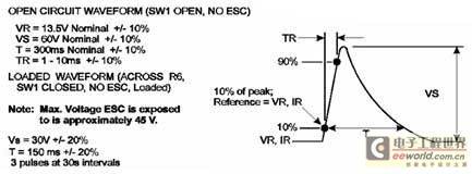
Figure 1 Definition of load power-off test
Although load dumps can cause load voltages to rise, most modern alternators are equipped with centrally controlled load disconnect clamps. The reference level is limited to between 35V and 42V for 12V bus systems and between 50V and 60V for 24V bus systems.
In cold weather, the starting device will cause the battery supply voltage to drop significantly. Figure 2 shows the typical waveform of a "cold start" test.
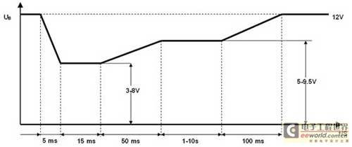
Figure 2 Typical waveform of a “cold start” test
Since the input power supply of the LED driver is connected to the input of the battery, automotive lights such as brake lights that involve driving safety must not be affected by load power failure and cold start, and must even be able to continue to operate normally under such circumstances. In typical cases, the input range of a 12V bus system is 6V to 42V, and the input voltage range of a 24V bus system is 12V to 60V.
LED drive technology
Resistor current limiting is one of the LED driving methods. Its advantages are low cost and simple design. Its disadvantages are that the current will change with the difference of forward voltage and driving voltage, so the brightness of the LED will change. When the battery voltage is relatively high, the driving efficiency is very poor because most of the power will be consumed in the resistor. In addition, the current limiting resistor will generate a lot of heat, leading to heat dissipation problems. So this is a simple but not the most efficient method.
The second method is a linear current stabilizer, also called a constant current source. Its advantages are simple design and constant current; its disadvantages are low efficiency, and as the input voltage increases, the voltage drop borne by the linear chip increases, so the linear chip will also generate a lot of heat. But it improves the disadvantage of current fluctuation in the resistor current limiting method.
In addition to the above two methods, there is also a switching power supply driving method. Table 1 is a comparison of the three different methods. The method of using a switching power supply as an LED driver has high efficiency and constant current. Due to the high efficiency of the switching power converter, it is used by more and more car lamp manufacturers. Its biggest disadvantage is that the design circuit is more complicated and the cost is relatively high.
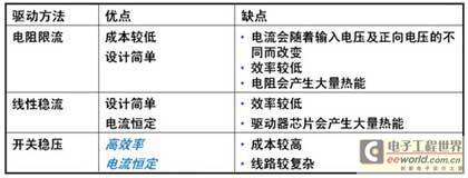
Table 1 Comparison of three LED driving methods
Why are boost/buck LED drivers used in automotive lighting? This is because the battery voltage fluctuates. When the voltage fluctuates, we need to keep the current flowing through the LED constant. The boost/buck LED driver can ensure that the current remains constant regardless of whether the input voltage is higher or lower than the output voltage. This ensures that safety-related lighting can maintain constant brightness when the load is powered off and cold started. In addition, diverse LED automotive lighting applications also require different LED driver topologies. Some automotive lighting manufacturers hope to have an LED driver platform that can be used for different LED configurations in different lighting systems. The boost/buck LED driver is an ideal driver solution for most high-brightness automotive lighting systems.
LM3423 (Figure 3) is a boost/buck LED driver chip from NS. It not only provides fast dimming control, reliable protection and fault display functions, but also can be configured with boost, floating buck and floating boost/buck LED drivers to meet different LED vehicle drive requirements.
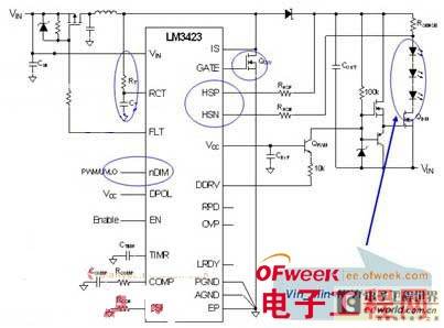
Figure 3 LM3423 step-up/step-down application schematic
Boost LED Driver for LED Backlight Systems
In general applications, we will use a boost constant current LED driver to drive multiple strings of a large number of LEDs. The LED backlight system with this configuration can provide backlight for the car dashboard and navigation system display. In addition, the car dashboard display must be equipped with a dimming control function to control the brightness of the LED backlight. For example, the brightness can be increased when the surrounding environment is bright, and it can be lowered when the surrounding environment is dark to prevent the driver's eyes from being unable to adapt to the rapid brightness change, affecting driving safety. In addition, the controller with PWM dimming function must have a good contrast, that is, it must have a good linear adjustment.
PWM signal is a series of pulse signals. We can control the emission of pulses by switching the current switch, so that the LED emits flashes of more than 100Hz. In this way, we will feel that the brightness has been reduced visually, because the human eye will filter/average the brightness. The quality of the dimming function is achieved through the duty cycle of the dimming. If the duty cycle of the device is very small, the dimming range will be larger and have better linearity. There are usually two methods: one is analog signal dimming, and the other is PWM signal dimming. Since analog dimming is achieved by changing the current of the LED, when the current of the LED changes, the color of the LED will also change, so we usually choose PWM dimming as the brightness control method. When this method is used, the LED is either turned on or off, and the color of the LED will not change.
LM3423 supports fast dimming control and "0" shutdown current function, which is suitable for LED backlight systems of car navigation system displays and instrument panels (Figure 4). It can ensure that the current flowing through each lamp is consistent. A MOS tube is connected in series under the LED as a switch for dimming control. Among them, the nDIM pin is responsible for executing input undervoltage lockout and PWM dimming functions. Whenever a PWM signal is input, the DDRV pin will drive the DIM N-FET and command the LEDs connected in series to switch quickly in order to control the brightness. The dimming control frequency can be as high as 50kHz.

Figure 4 LM3423 boost LED driver
Figure 5 shows a comparison of dimming effects. It can be seen that under very low duty cycle conditions, the same switch can be maintained and the current flowing through the LED is constant. The dimming duty cycle shown in the figure is 0.5%, the input voltage is 12V, the LED current is 100mA, and the number of drivers is 10 LEDs per string. The dimming frequency selected here is 230Hz. When the brightness of the surrounding environment dims, the LED backlight of the car display will lower the brightness of the light. If the duty cycle is very small, the brightness can be adjusted very low, and when the ambient brightness is very dark, the brightness of the dashboard will not feel very dazzling.
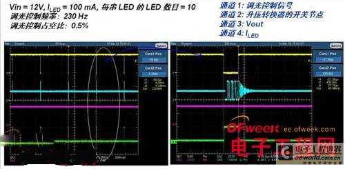
Figure 5 LM3423 dimming control effect comparison
When using a traditional boost mode driver, there is a problem: regardless of whether the controller driver is working or not, there is a path between its input and output. In this case, the battery at the input end will have a DC path to the load, which will cause leakage. When used for vehicle lighting, this path will discharge the battery when the car is not used for a long time. When the vehicle is started again, it will be found that the battery is dead. Another problem is that when a short circuit occurs at the output end, the battery will be discharged. Even if the main switch is turned off, it will not affect the leakage at the output end. In this case, a fuse should be added to the output end to prevent a short circuit. Using LM3423 can solve this problem and effectively extend the battery life. If the LED string is connected to the ground, forming a short circuit, the input end P-FET driven by the FLT pin will be turned off immediately, making the input path open and avoiding leakage problems.
Previous article:Analysis of three stages of LED development and four major technical problems
Next article:Isolation and non-isolation architecture considerations for LED lighting driver power supply
- MathWorks and NXP Collaborate to Launch Model-Based Design Toolbox for Battery Management Systems
- STMicroelectronics' advanced galvanically isolated gate driver STGAP3S provides flexible protection for IGBTs and SiC MOSFETs
- New diaphragm-free solid-state lithium battery technology is launched: the distance between the positive and negative electrodes is less than 0.000001 meters
- [“Source” Observe the Autumn Series] Application and testing of the next generation of semiconductor gallium oxide device photodetectors
- 采用自主设计封装,绝缘电阻显著提高!ROHM开发出更高电压xEV系统的SiC肖特基势垒二极管
- Will GaN replace SiC? PI's disruptive 1700V InnoMux2 is here to demonstrate
- From Isolation to the Third and a Half Generation: Understanding Naxinwei's Gate Driver IC in One Article
- The appeal of 48 V technology: importance, benefits and key factors in system-level applications
- Important breakthrough in recycling of used lithium-ion batteries
- Innolux's intelligent steer-by-wire solution makes cars smarter and safer
- 8051 MCU - Parity Check
- How to efficiently balance the sensitivity of tactile sensing interfaces
- What should I do if the servo motor shakes? What causes the servo motor to shake quickly?
- 【Brushless Motor】Analysis of three-phase BLDC motor and sharing of two popular development boards
- Midea Industrial Technology's subsidiaries Clou Electronics and Hekang New Energy jointly appeared at the Munich Battery Energy Storage Exhibition and Solar Energy Exhibition
- Guoxin Sichen | Application of ferroelectric memory PB85RS2MC in power battery management, with a capacity of 2M
- Analysis of common faults of frequency converter
- In a head-on competition with Qualcomm, what kind of cockpit products has Intel come up with?
- Dalian Rongke's all-vanadium liquid flow battery energy storage equipment industrialization project has entered the sprint stage before production
- Allegro MicroSystems Introduces Advanced Magnetic and Inductive Position Sensing Solutions at Electronica 2024
- Car key in the left hand, liveness detection radar in the right hand, UWB is imperative for cars!
- After a decade of rapid development, domestic CIS has entered the market
- Aegis Dagger Battery + Thor EM-i Super Hybrid, Geely New Energy has thrown out two "king bombs"
- A brief discussion on functional safety - fault, error, and failure
- In the smart car 2.0 cycle, these core industry chains are facing major opportunities!
- The United States and Japan are developing new batteries. CATL faces challenges? How should China's new energy battery industry respond?
- Murata launches high-precision 6-axis inertial sensor for automobiles
- Ford patents pre-charge alarm to help save costs and respond to emergencies
- New real-time microcontroller system from Texas Instruments enables smarter processing in automotive and industrial applications
- TMS320C665x program loading and burning based on emulator
- 31 "Millions of Miles" Raspberry Pi Car——Ubuntu MATE System Installation
- ABB six-axis robot and Siemens 1500PLC user manual
- [Ateli Development Board AT32F421 Review] 7. Kuga registers jointly light up OLED
- Design and FPGA implementation of digital on-screen display control core.pdf
- EL817C Optocoupler Transmission Ratio Problem
- Keysight Technologies N9020A 3.6G spectrum analyzer special sale: 8500/unit
- STM32+photosensitive sensor+serial port receiving light intensity source program is successfully produced
- How does the uart.write function output three bytes of 0XFF 0XFF 0XFF (HEX data, not string data)?
- Electric vehicles use silicon carbide power devices to successfully move out of the laboratory

 ST Power Management Guide


 京公网安备 11010802033920号