Program loading and burning based on emulator
Check whether the emulator is installed successfully
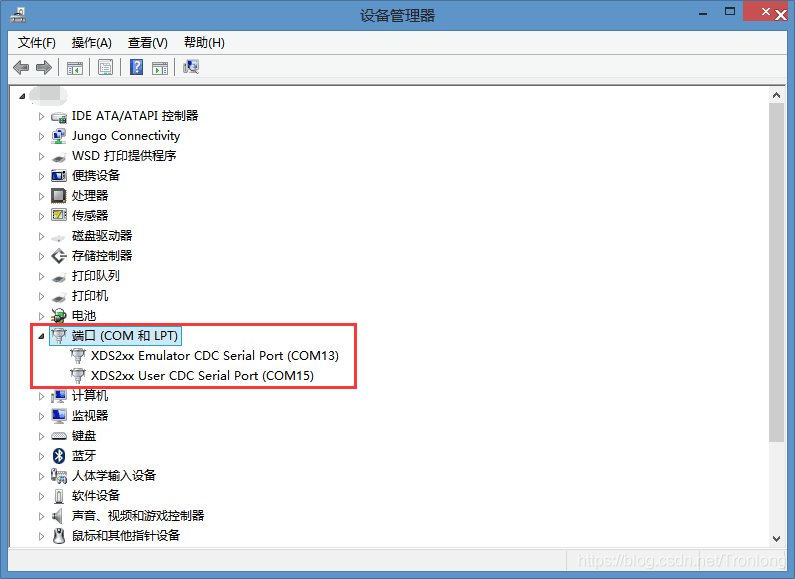
Power off the development board, connect the development board and the computer terminal with the emulator. Right-click the computer icon, click "Manage -> Device Manager -> Universal Serial Bus Controllers" or "Manage -> Device Manager -> Ports", and check whether there is an option for the corresponding emulator. If there is, it means that the emulator driver has been installed normally.

Figure 1

Figure 2
The CCS integrated development environment comes with XDS100 and XDS200 series emulator drivers. If the emulator cannot be used normally, please check whether there is a driver conflict. The XDS100 series emulator uses FTDI chips, please check whether it conflicts with the USB-to-serial port driver that has been installed using FTDI. If you use the XDS200 emulator, please check whether the USB-to-serial port driver is correctly installed in the computer or try to reinstall the computer motherboard chipset driver.
Set project configuration file information
Note: If you use the XDS220 emulator, its configuration method via USB is the same as the XDS200 configuration, but the XDS220 emulator has a network emulation function. For detailed configuration methods, please refer to Section 1.2.2: Network Emulation Configuration.
- Single emulator configuration
Please install CCS according to the software installation "Windows version CCS5.5 installation" document, then open the CCS integrated development environment, click the menu "File->New->Target Configuration File", as shown below:

Figure 3
In the pop-up interface, enter the name of the project configuration file and click Finish. As shown below:

Figure 4
In the pop-up dialog box, select the corresponding emulator type in the Connection drop-down box (for example, if you use the TL-XDS200 emulator, select "Texas Instruments XDS2xx USB Emulator_0"). In the "Board or Device" drop-down box, select the corresponding CPU model, TMS320C6657, TMS320C6655 or TM320C6654, and then click Save on the right to save the settings. As shown in the following figure:

Figure 5
Connect the emulator to the development board, and turn the DIP switch to NO BOOT mode, which is the DEBUG mode. After the development board is powered on, click "Test Connection" to test whether the emulator is connected successfully. As shown in the figure below:

Figure 6
- Network simulation configuration
The XDS220 emulator has the function of network emulation. The operation of network emulation configuration is as follows:
Connect one end of the network cable to the router and the other end to the network interface of the XDS220 emulator. In addition, the USB interface cable needs to be connected to the computer and the emulator to ensure that the emulator driver is installed normally.
Enter the CCS installation directory and enter the "ti\ccsv5\ccs_base\emulation\specdig" path. The specific path is based on your personal CCS installation path. You can see the xds2xx folder, as shown in the figure:

Figure 7
Select the xds2xx folder, hold down the Shift key, right-click, and select "Open command window here" in the pop-up window.

Figure 8
A command window will pop up. Enter the following command in the command window and press Enter.
DOS# xds2xx_conf set xds2xxu 0 ipConfig=dhcp

Figure 9
View the IP obtained by the emulator through the command line, enter the following command, press Enter, and you can see the cmd window print out the dynamic IP obtained by the emulator: 192.168.1.61.

Fig.10
Open CCS and click the menu "File->New->Target Configuration File", as shown below:

Fig.11
In the pop-up interface, enter the name of the project configuration file and click Finish. As shown below:

Fig.12
In the pop-up dialog box, select the corresponding emulator type in the "Connection" drop-down box, and select the corresponding CPU model in the "Board or Device" drop-down box, TMS320C6657, TMS320C6655 or TM320C6654. As shown in the following figure:

Fig.13
Select C66xx_0, click the Browse button in the right window, and load the gel file, as shown in the following two figures.

Fig.14
Load the gel file. The gel file is in the Image directory of the CD. When using it, you need to copy it to a non-Chinese path, as shown in the figure.

Fig.15
Select the simulator configuration and enter the IP address assigned to the simulator in the IP column: 192.168.1.61 (the specific IP address is subject to the allocation of your own server)

Fig.16
Click Test Connection and you will see a pop-up window. If the test is successful, it means the configuration is successful.

Fig.17
- Multiple emulator configurations
Open the newly created configuration file and click "Advanced->New...", as shown in the figure:

Fig.18
Select the corresponding emulator connection, as shown in the figure:

Fig.19
Click on the newly created emulator connection, and then click "Add...", as shown in the figure:

Fig. 20
Click the Devices window, select the corresponding chip, and click Finish, as shown in the figure:

Fig.21
Click the newly created simulator connection, modify the corresponding port value, and save it, as shown in the figure:

Fig. 22
You can continue to add multiple simulator configurations as above.
Loading GEL Files
GEL files are mainly used to initialize the CPU during simulation debugging, such as PLL, DDR, etc., and can also perform some debugging operations. The "Tronlong_C665x.gel" file is used for initialization in the example, and the configuration is as follows: CPU 1.0GHz, DDR3 equivalent frequency and CPU fan control.
Click the CCS menu "Run->Debug" and a similar interface will pop up. You can see the C66xx_0 core. If you are using TMS320C6657, you will also see the C66xx_1 core. Both the C66xx_0 and C66xx_1 cores can load GEL files and program images separately.

Fig.23
Right-click the corresponding DSP core and select the "Open GEL Files View" option in the pop-up interface. The "GEL Files (TMS320C66xx)" dialog box will pop up in the lower right corner.

Fig.24
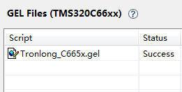
Right-click in the dialog box and select "Load GEL" in the pop-up interface. Select the GEL file "Tronlong_C665x.gel" in the Images directory of the CD data, and then click "Open". Then the "GEL Files (TMS320C66xx)" dialog box in the lower right corner will appear a Success prompt statement, as shown below:

Fig.25
CCS connects to the development board CPU
Right-click the corresponding DSP core and select the "Connect Target" option, and the Suspended status will be displayed. This means that CCS has been properly connected to the development board CPU, as shown in the following figure:

Fig.26
Note: If the message "No source****" is displayed here, it is not an error message and can be ignored.
After the connection is made, the development board will be automatically initialized, as shown below:

Fig. 27
The fan can be turned on and off under the Scripts menu, as shown in the figure.

Fig.28
Loader image file
Click "Run->Load->Load Program", select the program image file (the "MyC665x.out" file for demonstration is in the Images directory of the CD data, and the bottom panel LED light is lit), and click OK. Then click the green triangle start button  , and the program will run normally.

Fig.29

Fig.30
Burn the program to FLASH
Since the EEPROM of the development board is burned with IBL (Intermediate BootLoader), which is the secondary boot program, it supports directly starting the binary .out file in ELF format, so the generated .out file can be burned to NAND FLASH or NOR FLASH and run offline. Relying on the support of IBL, the .out file compiled in CCS can be burned directly without any conversion. It should be noted that the .out file contains a lot of debugging information, so the file is large. The specific burning steps are as follows.
- Load the burning tool program
If you need to burn NAND FLASH, copy the NandFlashWriter.out, nand_writer_input.txt files and the .out program to be burned in the "Demo\Flash Writer" directory of the CD to the same non-Chinese path, and change the name of the .out program file to be burned to app.bin.
If you need to burn NOR FLASH, copy the NorFlashWriter.out, nor_writer_input.txt files and the .out program to be burned in the "Demo\Flash Writer" directory of the CD to the same non-Chinese path, and change the name of the .out program file to be burned to app.bin.
Open the CCS integrated development environment, load the GEL file and connect the CPU, then load the burning tool program file NandFlashWriter.out or NorFlashWriter.out, and click OK, as shown below:

Fig.31
Click "View->Memory Browser" in the CCS menu bar, click the "Save Memory" button in the pop-up interface, and then select "Load Memory" in the drop-down box, as shown in the following figure:

Fig.32
Select the program file and select "Raw Data Format (.bin)" as the file type, as shown below:

Fig.33
Click Next, enter the starting address in the pop-up interface: 0x80000000, select the data type: 32 bits, then click Finish and wait for the loading to complete, as shown below:

Fig.34
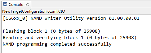
Click the Run button  to start burning the program. After the burning is successful, the Console prompt information is similar to the following figure:

Fig.35
Unplug the emulator, put the development board into the corresponding startup position, and the program will run normally.
Burning multi-core and multi-image files
The GEL file here uses the DSP_C665x.gel file in the "Demo\TargetConfig" folder. Please install Python 2.x or above in advance, and the installation program is in the folder "Demo\HostApp".
The following steps are used to burn multi-core multi-image files to NAND FLASH. The specific burning steps are as follows (some similar burning steps refer to the above subsections, and the key steps are described here).
- Generate a single flashable file
In the "Demo\HostApp\MultiCoreBoot\Image Create\Config" folder, use WordPad to open the deployment_C6657_bypass_prelink.json file, modify the corresponding multi-core image file path, and then save and close it, as shown in the figure:

Fig.36
Return to the previous directory, open the Build.bat file in edit mode, modify the path of the C6000 compiler tool and the installation path of Python, save and close. Double-click the Build.bat file again to generate a single programmable file C6657-le.bin, which is saved in the newly generated images folder at the same level.

Fig.37
Open the DSP_C665x.gel file, change the boot image format from the default ibl_BOOT_FORMAT_ELF to ibl_BOOT_FORMAT_BBLOB, and save it.

Fig.38
Connect the development board CPU, load the i2cparam_0x50_c6657_le_0x500.out file, and save it in the folder "Demo\HostApp\MultiCoreBoot\IBL Config".

Fig.39
Click Run first, then click "Scripts->EVM TL665x IBL->SetConfig_TL665x_main".

Fig.40
Then in the Console window, press the Enter key and the modification is successful, as shown in the following figure:

Fig.41
You can also control the boot mode and CPU fan action through IBL configuration. Modify the value of ibl.EvmConfig.Fan in the DSP_C665x.gel file, TRUE is on, FALSE is off.

Fig.42
All Rom boot modes are supported through IBL configuration. The reference document in the CD contains "DSP C665x Boot Mode Summary". When ibl.RomBoot.Enable=TRUE; IBL will modify the boot configuration register according to the value set by ibl.RomBoot.Mode and then jump to Rom Bootloader to execute the remaining boot process (note that IBL boot will not be executed at this time, so if IBL boot is required, this configuration item should be set to FALSE). Set ibl.RomBoot.Mode=0x00001811 as shown in the figure (only the lower 16 bits are valid):

Fig.43
The lower 16 bits 0x1811 = 0001100000010001b. At this time, starting the development board is equivalent to starting from RBL UART0 from the user's perspective. At this time, you can see that the serial port 0 prints "cccc.....". During this period, the boot table format executable program can be transmitted to the development board through the serial port 0 to complete the boot.

Fig.44
- Loading multi-core image files
Follow the steps to load the programming tool program, modify the C6657-le.bin program file name to app.bin, and then load the multi-core image file.
Click the Run button  to start burning the program. After the burning is successful, the Console prompt information is similar to the following figure:

Fig.45
Unplug the emulator, put the development board into the corresponding startup position, and the program will run normally.
Software Simulation
When using CCS to simulate program operation, users can verify the program without connecting hardware or simulator, which is suitable for programs that focus on algorithms.
- Set project configuration file information
Project configuration: Select Texas Instruments Simulator for Connection, select the corresponding platform for Broad or Device, and click Save on the right to save the configuration, as shown in the following figure:

Fig.46
Load the image according to the program loading steps to perform software simulation.


 Room 1530, Zhongguancun MOOC Times Building,
Block B, 18 Zhongguancun Street, Haidian District,
Beijing 100190, China
Tel:(010)82350740
Postcode:100190
 京公网安备 11010802033920号


 提升卡
提升卡 变色卡
变色卡 千斤顶
千斤顶