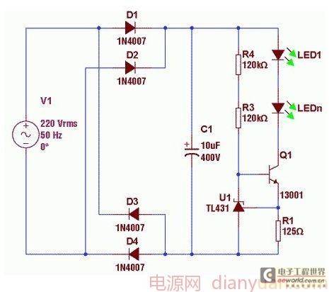
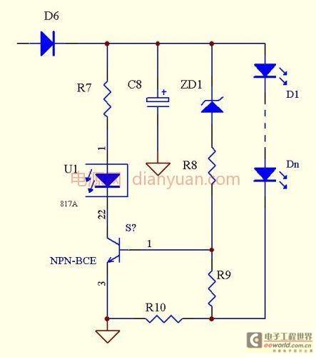
The principle in the figure below is to control the current in the LED by changing the IB current of the transistor , which also has the disadvantage of high loss.
Main advantages and disadvantages analysis:
The circuit is simple and reliable, and the low cost is its biggest advantage; the constant current accuracy is not high, and the temperature drift is serious is its biggest disadvantage.
 Targeted questions and answers:
wwpp asks: What is D7? How to keep constant current?
Answer: For Schottky tube, D7 has the same temperature drift characteristics as Q1, which can offset the influence of temperature drift of Q1. As for constant current, you can think about the be junction voltage drop of Q1, and then look at the voltage drop of D7 and R10, and you will understand.
wzpawzz asked: Brother Bing, I want to ask you, I am now making a constant current and voltage limiting source, but the constant current value of the output current can be adjusted, and the adjustment range is 150ma to 350ma.
The LED driver I made is isolated and uses flyback. But how can the detection circuit be isolated? I want to use a small resistor in series with the load to detect the change in its voltage. This detection is completed by the microcontroller, which is AD sampling. The microcontroller outputs the corresponding PWM wave based on the sampled value to control the on and off of the primary switch tube. I don't know how to isolate the feedback control?
My own idea:
1. Since the maximum current of my constant current source is 350ma, and the maximum input current of the optocoupler PC817 is 50ma, I can use many optocouplers in parallel to connect them in series on the constant current source to sense the change of current. The output current of each optocoupler is then combined and flows through a resistor to achieve the conversion of current to voltage for sampling by the microcontroller. Feasibility analysis: If 10 optocouplers are added, the current flowing through each at the maximum constant current is 35ma, and the forward voltage of the diode inside the optocoupler is about 1.2V, then the loss is 0.035*1.2*10=420mw, and the optocoupler output also has loss, so this solution has too much loss and is not advisable!
2. Use a small resistor in series with the constant current load, and the microcontroller detects the change of current through AD sampling, outputs PWM wave, and then adds an isolation transformer to the driving circuit. However, I am afraid that this isolation transformer will cause PWM distortion and cannot control the switch tube well?
3. Use a small resistor in series with the constant current load, and then use an op amp to follow and amplify. The output of the op amp is connected to PC817 and connected in series with a resistor. Then when the voltage on the detected small resistor changes, the current of the optocoupler will change. Then I connect a resistor to the E pole of the output end of the optocoupler, and the C pole to a 5V power supply. The change in the optocoupler current will cause the change in the voltage at the resistor end on the E end. The microcontroller samples this voltage change and performs PWM control. Feasibility analysis: If the resistance of the small resistor in series on the load is 0.1 ohms, then the minimum voltage across it is only about 15mv. To amplify the signal, the op amp has high requirements, and 358 is definitely not enough. I think other isolation and detection can be achieved. What do you think?
My load is 5 to 10 1w LED lights. If the output voltage is greater than 36 volts, it is a constant voltage output, and if it is less than 36 volts, it is a constant current output. What is different from the post is that my constant current must be adjustable, not fixed, and the PWM control function is realized by a single-chip microcomputer.
Answer: You mentioned three options, which shows that you are a person who is willing to think about problems.
But in fact it is not that complicated. Ordinary PWM IC can be used for primary control, and low-resistance resistors can be used for secondary cross-current sampling. If available, add a differential amplifier, and then compare the output with the reference to drive the optocoupler, which is transmitted to the primary side to control the duty cycle of the PWM IC. If you want to adjust the constant current value, you only need to change the reference voltage to meet the requirement.
Previous article:Engineers' technical sharing: Design of LED driver circuit without electrolytic capacitor
Next article:Built-in LED fluorescent lamp design with high-brightness LED white light source
Recommended ReadingLatest update time:2024-11-23 07:24


- Popular Resources
- Popular amplifiers
- RAQ #223: How to measure and determine soft-start timing without a soft-start equation?
- Vicor high-performance power modules enable the development of low-altitude avionics and EVTOL
- Bourns Launches Two Thick Film Resistor Series with High Power Dissipation Capabilities in Compact TO-220 and DPAK Package Designs
- Bourns Launches New High-Pulse Brake Resistor Series with Superior Energy Dissipation Capabilities
- Nexperia launches new 120 V/4 A half-bridge gate driver to further improve robustness and efficiency in industrial and automotive applications
- Vishay's New 150 V MOSFETs Offer Industry-Leading Power Loss Performance
- The first generation of SGT MOSFET series from Qiangmao: innovative trench technology, automotive-grade 60 VN channel, breakthrough in high-efficiency performance of automotive electronics
- DC/DC Power Supplies for Automotive Applications
- MathWorks and NXP Collaborate to Launch Model-Based Design Toolbox for Battery Management Systems
- Intel promotes AI with multi-dimensional efforts in technology, application, and ecology
- ChinaJoy Qualcomm Snapdragon Theme Pavilion takes you to experience the new changes in digital entertainment in the 5G era
- Infineon's latest generation IGBT technology platform enables precise control of speed and position
- Two test methods for LED lighting life
- Don't Let Lightning Induced Surges Scare You
- Application of brushless motor controller ML4425/4426
- Easy identification of LED power supply quality
- World's first integrated photovoltaic solar system completed in Israel
- Sliding window mean filter for avr microcontroller AD conversion
- What does call mean in the detailed explanation of ABB robot programming instructions?
- STMicroelectronics discloses its 2027-2028 financial model and path to achieve its 2030 goals
- 2024 China Automotive Charging and Battery Swapping Ecosystem Conference held in Taiyuan
- State-owned enterprises team up to invest in solid-state battery giant
- The evolution of electronic and electrical architecture is accelerating
- The first! National Automotive Chip Quality Inspection Center established
- BYD releases self-developed automotive chip using 4nm process, with a running score of up to 1.15 million
- GEODNET launches GEO-PULSE, a car GPS navigation device
- Should Chinese car companies develop their own high-computing chips?
- Infineon and Siemens combine embedded automotive software platform with microcontrollers to provide the necessary functions for next-generation SDVs
- Continental launches invisible biometric sensor display to monitor passengers' vital signs
- GD32E231 DIY Competition (3) - Driving LCD5110
- Energy-saving design of display screens has become a key research area for power management
- How to debug an application using J-Link's Infinite Flash breakpoint feature?
- Getting Started with MCU
- How to decode asynchronous LVDS data using Xilinx FPGA?
- A brief discussion on new Wi-Fi 7 technologies
- Several Issues on Application Programming of C51 Language
- Four hot application technologies in China from IIC-China 2006
- 8. "Wanli" Raspberry Pi car - socket learning (local communication)
- Want to buy used AES-ULTRA96-G


 Siemens PLC Project Tutorial
 LED Cube Code
 ESP32-S3 source code


 京公网安备 11010802033920号