High-power LEDs are widely used mainly due to their long life, small size, high power conversion efficiency, and high color temperature. However, in the promotion and application of LEDs, efficient and stable heat dissipation has become an important obstacle. This article focuses on the heat dissipation problem of high-power LEDs.
0 Introduction
LED was developed in 1962, and since then, orange, blue, red, green, ultraviolet, and infrared diodes have been successfully developed. At first, visible light emitting diodes were used for display light sources, such as road sign lights, brake lights, traffic lights, large-area color displays, etc. Of course, with the continuous improvement and progress of LED manufacturing technology, and the extensive development and application of new materials, LED has developed from monochrome to white, and gradually turned from signal display to lighting source. The performance of white light LED semiconductor solid light source has been continuously improved and has now entered the practical stage.
1 Principle of LED
The core part of LED is a chip composed of n-type semiconductor and p-type semiconductor, which is made by injection light-emitting principle. There is a transition layer of pn junction between n-type and p-type semiconductors. When the injected majority carriers and minority carriers recombine, the excess energy will be released in the form of light in some semiconductor materials, thus converting electrical energy into light energy. If the voltage is applied in the reverse direction, it will be difficult to inject minority carriers, so no light will be emitted.
LEDs are composed of Group V and Group III elements in the periodic table and are made of compound semiconductor materials. For example, gallium phosphide and gallium arsenide are commonly used materials for monochrome LEDs.
At present, gallium nitride is the main material for manufacturing white light LEDs. As for GaN thin film materials, there is no bulk single crystal GaN that can be homogeneously epitaxially grown. It is mainly grown on related special-shaped supporting substrates by organic metal vapor deposition. Materials such as n-A1GaN, p-A1GaN, and n-GaN are plated on the bottom of the substrate in turn, and then a series of processes are used, such as:
Packaging and dicing are used to complete the manufacturing process. This process is currently mature, but since sapphire is the main substrate material for GaN-based LEDs, no substrate material that can replace it has yet been found.
2 Importance of high power LED heat dissipation
The power of traditional tube core is relatively small, and the heat dissipation is not much, so there is no serious problem in heat dissipation. However, high-power LED is different. Its chip power density is very high. At present, due to the reasons of semiconductor manufacturing technology, more than 80% of the input power is converted into heat energy, and less than 20% is converted into light energy. If the heat of the chip is simply enlarged in proportion to the package size, it cannot be dissipated, and it is very likely to cause the solder to melt, causing the chip to fail, and accelerating the aging of the phosphor and chip is inevitable. The color of the LED will also deteriorate when the temperature rises. Heat dissipation is of great significance to LEDs. Generally, the junction temperature is required to be below 110° C to ensure the service life of the device.
At present, the primary issue that needs to be considered in high-power LED packaging is how to improve the heat dissipation problem caused by the increasing chip power. At present, there are two commonly used methods to improve the heat dissipation problem of LEDs, namely: speeding up the dissipation of internal heat, improving the heat dissipation structure of LEDs, so that the temperature of the chip can be effectively reduced; fundamentally reducing the generation of heat, improving the luminous efficiency of the chip, and improving the quantum efficiency of the device.
3 Common methods to speed up LED heat dissipation
3.1 Use materials with good thermal conductivity
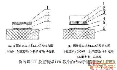
Regardless of the soldering method used, the chip needs to be bonded to the metal heat sink through the bonding material (as shown in Figure 1). In other words, if the bonding material can have higher thermal conductivity, the thickness of the bonding material layer can be reduced, thereby significantly improving the heat dissipation capacity of the device and significantly reducing the thermal resistance of the flip-chip LED. Relevant professionals used the finite element method to simulate the spatial temperature field distribution of flip-chip high-power white light LEDs and obtained the distribution surface diagram of the chip temperature. It was found that the temperature difference between the bottom metal heat sink and the bonding part of the chip is large, which means that there is a large thermal resistance in this area. If we can find a material with better thermal conductivity when bonding, the thermal resistance of the device will be effectively reduced.

3.2 Flip-chip soldering
At present, the commonly used flip-chip and face-mounted LED chip power structure schematic diagram (as shown in Figure 1). The flip-chip chip structure is developed to further improve the light output efficiency and heat dissipation capacity of power LED devices. The medium for device heat conduction uses Si material with high thermal conductivity, and the LED chip is bonded to the Si substrate through flip-chip technology. This is the characteristic of the flip-chip structure. Compared with the face-mounted structure, the flip-chip LED chip structure can transfer heat directly from the welding layer to the Si substrate without passing through the sapphire substrate, and then directly from the bonding material and the Si substrate to the metal base. The thermal conductivity of Si material is also relatively high, which further improves its heat dissipation capacity and can effectively reduce the thermal resistance of the device. In terms of improving the heat dissipation capacity of the device and reducing thermal resistance, the flip-chip structure has extremely obvious potential advantages.
3.3 Using a radiator for heat dissipation
Water cooling, heat pipe technology, air cooling, micro-channel cooling, etc. are currently the more commonly used cooling technologies.
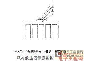
Air-cooled heat sinks are the most direct, simple, and lowest-cost way to dissipate heat for electronic chips. Schematic diagram of air-cooled heat sinks (as shown in Figure 2). In most medium and low-power electronic devices or devices, air cooling or forced air cooling technology is generally used, because the principle of air-cooled heat sinks is very simple: the heat dissipated by the chip is transferred to the metal base through the adhesive material, and then transferred from the metal base to the heat sink, and finally the heat is dissipated into the air through forced convection or natural convection. Convection and conduction are two important ways of heat transfer. We can use the following methods to enhance convection heat dissipation and conduction, and transfer the heat dissipated by the chip to the atmospheric environment under allowable temperature conditions.

3.3.1 Increase heat dissipation
The larger the heat dissipation area, the greater the heat capacity of the radiator. The factor that has an important impact on the heat dissipation effect of the radiator is the convection area determined by different fin spacing and fin height. The heat transfer coefficient, internal airflow organization, and application characteristics of the radiator are all directly affected by the fin layout. The turbulence created by the corrugated fin surface can further improve the heat transfer coefficient.
In view of the shortcomings of the flat fin square heat sink, relevant experts have proposed a composite heat sink with nail columns. Under the same wind speed, the surface Nusselt number of the fin-column heat sink is 30% to 45% higher than that of the plate-fin heat sink. Under the same pumping power, the benefit factor of the fin-column heat sink is also about 20% higher than that of the plate-fin heat sink. It can be seen that the fin-column heat sink has better heat dissipation performance, higher reliability, and lower use cost under roughly the same working conditions, and its use value is relatively high in cooling electronic equipment.
3.3.2 Use materials with relatively good thermal conductivity to make heat sinks
Copper and aluminum have become the commonly used radiator materials. Relatively speaking, aluminum has a low density, good thermal conductivity, low cost and easy processing. The thermal conductivity of copper is greater than that of aluminum. Many radiators made of pure copper have super heat dissipation capabilities, but copper materials are easily oxidized, and the processing and material costs are high. Combining the characteristics of copper and aluminum, aluminum is used as the heat sink and copper is used as the bottom. A composite radiator with good economy and high heat dissipation performance has emerged.
3.3.3 Forced cooling
In order to improve airflow organization, improve heat dissipation effect, speed up the flow of air around the heat sink, and increase the convection heat transfer coefficient, it is necessary to select a suitable blower or fan.
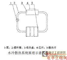
Relatively speaking, the heat dissipation efficiency of water cooling (liquid cooling) is relatively high, and compared with air cooling, it does not have the disadvantage of high noise, and the thermal conductivity can reach more than 20 times that of traditional air cooling, which is effective in solving noise and cooling. The water cooling device can be roughly divided into the above four parts: circulation pipe, heat sink, micro water pump, circulation pipe. The working principle of water cooling (as shown in Figure 3) is relatively simple. The heat dissipation device generates power through a pump, thereby circulating the liquid in a closed system. Through the continuous circulation of the liquid, the heat generated by the heat absorption and chip is transferred to the heat dissipation device with a larger surface area. It is a closed liquid circulation heat dissipation device. After the liquid is cooled, it will flow back to the heat absorption device, and the work will be repeated in this way.

4 Conclusion
For a single-chip LED, the more heat sinks there are, the larger the heat dissipation area is, and the lower the thermal resistance and junction temperature of the chip are. Reducing the thickness of the bonding material and increasing the thermal conductivity of the bonding material can reduce the thermal resistance and junction temperature of the chip, which is beneficial to dissipating the heat of the chip. Increasing the number of fins and increasing the diameter of the fins are extremely beneficial to reducing the thermal resistance and junction temperature of the chip. With the increase of the heat dissipation area, when the heat dissipation area is small, the thermal resistance and junction temperature of the chip will drop sharply. When the heat dissipation area increases to 0.012 square meters, the thermal resistance and junction temperature of the chip will decrease with the increase of the area. When the heat dissipation area continues to increase to 0.024 square meters, if the heat dissipation area continues to increase, the thermal resistance and junction temperature of the chip will not decrease. With the increase of ambient temperature, the junction temperature of the chip will rise linearly, and the thermal resistance of the same heat sink will not be affected by the ambient temperature. With the increase of the loading power, the junction temperature of the chip will increase linearly, and the loading power has only a small effect on the thermal resistance.
Previous article:Introducing DC drive power LED dimming technology
Next article:Count the technical features of full-color LED display
- Popular Resources
- Popular amplifiers
- MathWorks and NXP Collaborate to Launch Model-Based Design Toolbox for Battery Management Systems
- STMicroelectronics' advanced galvanically isolated gate driver STGAP3S provides flexible protection for IGBTs and SiC MOSFETs
- New diaphragm-free solid-state lithium battery technology is launched: the distance between the positive and negative electrodes is less than 0.000001 meters
- [“Source” Observe the Autumn Series] Application and testing of the next generation of semiconductor gallium oxide device photodetectors
- 采用自主设计封装,绝缘电阻显著提高!ROHM开发出更高电压xEV系统的SiC肖特基势垒二极管
- Will GaN replace SiC? PI's disruptive 1700V InnoMux2 is here to demonstrate
- From Isolation to the Third and a Half Generation: Understanding Naxinwei's Gate Driver IC in One Article
- The appeal of 48 V technology: importance, benefits and key factors in system-level applications
- Important breakthrough in recycling of used lithium-ion batteries
- LED chemical incompatibility test to see which chemicals LEDs can be used with
- Application of ARM9 hardware coprocessor on WinCE embedded motherboard
- What are the key points for selecting rotor flowmeter?
- LM317 high power charger circuit
- A brief analysis of Embest's application and development of embedded medical devices
- Single-phase RC protection circuit
- stm32 PVD programmable voltage monitor
- Introduction and measurement of edge trigger and level trigger of 51 single chip microcomputer
- Improved design of Linux system software shell protection technology
- What to do if the ABB robot protection device stops
- Allegro MicroSystems Introduces Advanced Magnetic and Inductive Position Sensing Solutions at Electronica 2024
- Car key in the left hand, liveness detection radar in the right hand, UWB is imperative for cars!
- After a decade of rapid development, domestic CIS has entered the market
- Aegis Dagger Battery + Thor EM-i Super Hybrid, Geely New Energy has thrown out two "king bombs"
- A brief discussion on functional safety - fault, error, and failure
- In the smart car 2.0 cycle, these core industry chains are facing major opportunities!
- The United States and Japan are developing new batteries. CATL faces challenges? How should China's new energy battery industry respond?
- Murata launches high-precision 6-axis inertial sensor for automobiles
- Ford patents pre-charge alarm to help save costs and respond to emergencies
- New real-time microcontroller system from Texas Instruments enables smarter processing in automotive and industrial applications
- After CC2541 is in master mode and searches for slaves to connect, the host can receive the data sent by the slave, but the slave cannot receive the data sent by the master?
- Review summary: Beetle ESP32-C3 free review
- Altiumdesigner 09 import Gerber file with fewer layers
- MSP430F1232 interrupt learning
- How to calculate power line width and overcurrent
- Constant voltage source adjustable voltage regulated power supply
- EEWORLD University Hall----Live Replay: Use dedicated IoT hardware and software solutions to start the journey from embedded to cloud
- RF GaN-on-Si: The Best of Both Worlds
- 1. [Record] Solve the copy and paste problem between Linux virtual machine and Windows on VMware
- Maxwell's Equations 3D Animation

 NJM082BV-(TE1)


 京公网安备 11010802033920号