Every DC/DC IC (whether step-up or step-down) can be connected to drive a constant current LED. Now we will take KZW3688 and CE9908 as examples to introduce their connection methods and characteristics.
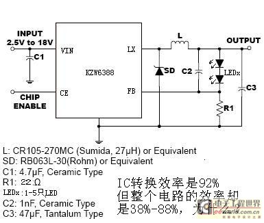
1. KZW3688 step-down IC, its connection method is as follows:

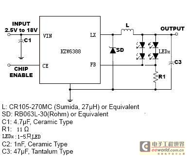
The principle is very simple, and you will know it at a glance, so I won't repeat it here. The value of R1 is calculated as 3.3V/required current. The figure above shows 2-5 connected, and multiple circuits can also be used in parallel. And here is a question for everyone: Is C2 needed? Take a look at the connection method in the figure below:

I removed C2 and connected one or even several LED strings in parallel. What do you think of the effect? Are you interested in answering?
There are too many circuits suitable for this connection method. In addition to 3688, any step-down IC such as PT1102, 1101, lm2596, GA8512, 1016, 1014, 313, 1011, etc. can be connected into such a circuit. The conversion efficiency of this circuit is as high as over 95%, but in actual use, the efficiency is between 36% and 88%, which is not as high as some targeted linear efficiency. Why is this? At the same time, it is pointed out that many constant current circuits write the efficiency of the LED drive circuit as the efficiency of IC conversion. This is wrong and misleading. It is hoped that engineers will pay attention to the parameters in these materials.
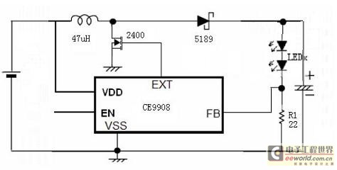
2. Boost IC, taking CE9908 as an example, the connection method is as follows:

Think about the principle. The connection method can also be to connect them in series first, and then connect the series in parallel to form N branches. Here I intentionally do not talk about the power factor, but only talk about the efficiency. This efficiency is also between 36-88%. Do you understand now? The efficiency of the IC that we regard as "high efficiency" in our hearts actually acts on the LED, and it must be measured in practice.
These two diagrams are just to illustrate the principles. They should be used flexibly in use. I believe that everyone will master more skills, such as using an external MOS tube to directly use a low-voltage step-down IC to connect to a 220V direct input AC/DC method (similar to 9910), using a lower sampling voltage (FB terminal) to improve the efficiency of the entire circuit, using parallel resonance combined with IC characteristics, and targeted design of efficient and high-quality LED drive circuits.
Previous article:LED Flash Solutions for Camera Phones
Next article:Recommendation of excellent LED driver ICs
Recommended ReadingLatest update time:2024-11-16 20:22


- Popular Resources
- Popular amplifiers
-
 西门子S7-12001500 PLC SCL语言编程从入门到精通 (北岛李工)
 -
 New Energy Vehicle Detection and Diagnosis Experiment (Edited by Mao Caiyun, Zhou Xien, and Long Jiwen)
 -
 Virtualization Technology Practice Guide - High-efficiency and low-cost solutions for small and medium-sized enterprises (Wang Chunhai)
 -
 ESP32-S3 source code
- MathWorks and NXP Collaborate to Launch Model-Based Design Toolbox for Battery Management Systems
- STMicroelectronics' advanced galvanically isolated gate driver STGAP3S provides flexible protection for IGBTs and SiC MOSFETs
- New diaphragm-free solid-state lithium battery technology is launched: the distance between the positive and negative electrodes is less than 0.000001 meters
- [“Source” Observe the Autumn Series] Application and testing of the next generation of semiconductor gallium oxide device photodetectors
- 采用自主设计封装,绝缘电阻显著提高!ROHM开发出更高电压xEV系统的SiC肖特基势垒二极管
- Will GaN replace SiC? PI's disruptive 1700V InnoMux2 is here to demonstrate
- From Isolation to the Third and a Half Generation: Understanding Naxinwei's Gate Driver IC in One Article
- The appeal of 48 V technology: importance, benefits and key factors in system-level applications
- Important breakthrough in recycling of used lithium-ion batteries
- Innolux's intelligent steer-by-wire solution makes cars smarter and safer
- 8051 MCU - Parity Check
- How to efficiently balance the sensitivity of tactile sensing interfaces
- What should I do if the servo motor shakes? What causes the servo motor to shake quickly?
- 【Brushless Motor】Analysis of three-phase BLDC motor and sharing of two popular development boards
- Midea Industrial Technology's subsidiaries Clou Electronics and Hekang New Energy jointly appeared at the Munich Battery Energy Storage Exhibition and Solar Energy Exhibition
- Guoxin Sichen | Application of ferroelectric memory PB85RS2MC in power battery management, with a capacity of 2M
- Analysis of common faults of frequency converter
- In a head-on competition with Qualcomm, what kind of cockpit products has Intel come up with?
- Dalian Rongke's all-vanadium liquid flow battery energy storage equipment industrialization project has entered the sprint stage before production
- Allegro MicroSystems Introduces Advanced Magnetic and Inductive Position Sensing Solutions at Electronica 2024
- Car key in the left hand, liveness detection radar in the right hand, UWB is imperative for cars!
- After a decade of rapid development, domestic CIS has entered the market
- Aegis Dagger Battery + Thor EM-i Super Hybrid, Geely New Energy has thrown out two "king bombs"
- A brief discussion on functional safety - fault, error, and failure
- In the smart car 2.0 cycle, these core industry chains are facing major opportunities!
- The United States and Japan are developing new batteries. CATL faces challenges? How should China's new energy battery industry respond?
- Murata launches high-precision 6-axis inertial sensor for automobiles
- Ford patents pre-charge alarm to help save costs and respond to emergencies
- New real-time microcontroller system from Texas Instruments enables smarter processing in automotive and industrial applications
- What is the purpose of adding a capacitor to the source and drain of a MOS tube?
- FPGA Design Tips
- Antenna Basics-Huawei
- Introduction to the development history of ARM architecture
- [Infineon XENSIV PAS CO2 sensor] Simple unboxing
- An article to understand the analysis and calculation of electrolytic capacitor life
- FreeRTOS in the JIHAI APM32E103VET6 review
- Wu Jianying's live video sharing of microcontroller lectures
- ESP32-C3 Debug Diary
- LPS28DFW driver and related information

 西门子S7-12001500 PLC SCL语言编程从入门到精通 (北岛李工)
 ESP32-S3 source code


 京公网安备 11010802033920号