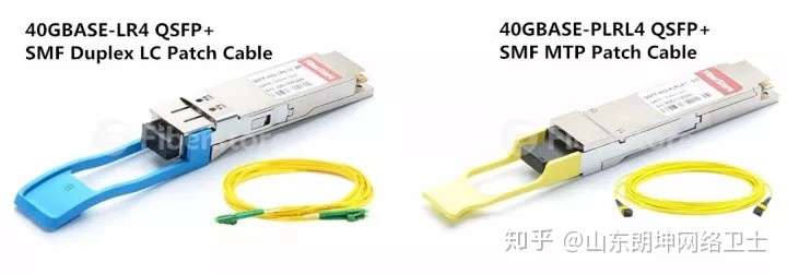
SFP module refers to various types of optical modules available (such as SFP+, QSFP, etc.). For this type of module, how can we determine whether the SFP module is working properly? We can use Fluke fiber optic tester to measure the optical power emitted by SFP and SFP itself.
Here, we take the new Versiv2-based CertiFiber Pro fiber loss certification analyzer CFP2-100-Q as an example (CFP-100-Q is a single-mode and multimode integrated tester, CFP-100-M is a multimode fiber tester, and CFP-100-S is a single-mode fiber tester). First, set the CertiFiber Pro tester CFP2-100-Q to "power meter" mode. Select the TOOLS menu on the main screen, and then select the second option. If a CertiFiber Pro module is connected, the option is POWER METER. After selecting this option, you will directly enter the power meter function. The power meter function will automatically start and run without pressing the TEST key.
We need to apply a few simple configurations. Note the lower half of the power meter. The upper half is for transmit and is not needed when testing SFPs. All we need to pay attention to is the absolute power output. I prefer to read the dBm data because it reflects the technical specifications of many SFP modules.

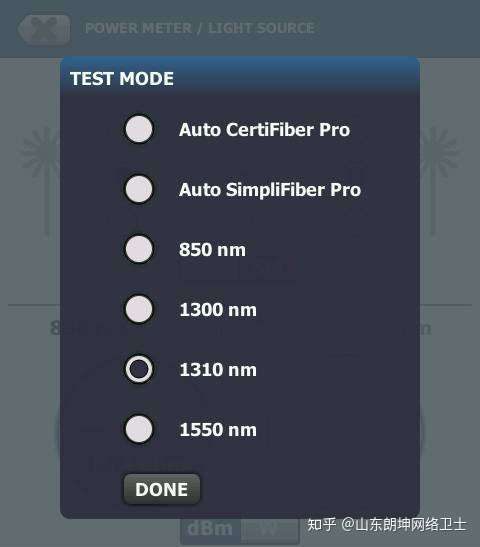
One of the important configurations is the λ (Lambda) or wavelength, located in the lower left corner. What are you testing? If it is multimode - select 850; if it is single mode - select 1310. Press the λ (Lambda) key and select the correct wavelength from the pop-up menu (see the figure below).

Check with the SFP manufacturer for acceptable power levels. Note that if you get a positive number, you will need to add attenuators to your system.
How do I check if an SFP port is clean? There is actually no way to do a particularly effective inspection of an SFP module. Inspection microscopes and related standards such as IEC 61300-3-35 are designed for the connector, not the output port of the SFP. The input port of the SFP should be some type of non-contact large-area input port. The fiber does not actually touch the port directly, so it should be kept fairly clean. Even if there is dust or other debris on the port, it is difficult to see with a microscope.

What if we use QSFP to send 40G through MPO connectors? How to test it? There are two simple options. One is to use a fan-out cable to connect the MPO port to multiple branches of LC connectors. Then plug it into the CertiFiber Pro.
Another option is to plug the MPO cable directly into the MultiFiber Pro . Set it to "Power" mode and you will get the power level of each fiber. This is an example with only one optical receive channel. Click here to learn more about the MultiFiber Pro MPO fiber tester.

Note that if you are working at 40G, you are most likely only using 4 fibers, so don't be surprised if you only see power levels on the first or last 4 fibers on your power meter.
Previous article:Analysis of the Differences between Fiber OTDR Testing and Optical Loss Testing
Next article:How to read the Fluke DSX-5000 CH test report
- Popular Resources
- Popular amplifiers
- From probes to power supplies, Tektronix is leading the way in comprehensive innovation in power electronics testing
- Seizing the Opportunities in the Chinese Application Market: NI's Challenges and Answers
- Tektronix Launches Breakthrough Power Measurement Tools to Accelerate Innovation as Global Electrification Accelerates
- Not all oscilloscopes are created equal: Why ADCs and low noise floor matter
- Enable TekHSI high-speed interface function to accelerate the remote transmission of waveform data
- How to measure the quality of soft start thyristor
- How to use a multimeter to judge whether a soft starter is good or bad
- What are the advantages and disadvantages of non-contact temperature sensors?
- In what situations are non-contact temperature sensors widely used?
- LED chemical incompatibility test to see which chemicals LEDs can be used with
- Application of ARM9 hardware coprocessor on WinCE embedded motherboard
- What are the key points for selecting rotor flowmeter?
- LM317 high power charger circuit
- A brief analysis of Embest's application and development of embedded medical devices
- Single-phase RC protection circuit
- stm32 PVD programmable voltage monitor
- Introduction and measurement of edge trigger and level trigger of 51 single chip microcomputer
- Improved design of Linux system software shell protection technology
- What to do if the ABB robot protection device stops
- Analysis of the application of several common contact parts in high-voltage connectors of new energy vehicles
- Wiring harness durability test and contact voltage drop test method
- From probes to power supplies, Tektronix is leading the way in comprehensive innovation in power electronics testing
- From probes to power supplies, Tektronix is leading the way in comprehensive innovation in power electronics testing
- Sn-doped CuO nanostructure-based ethanol gas sensor for real-time drunk driving detection in vehicles
- Design considerations for automotive battery wiring harness
- Do you know all the various motors commonly used in automotive electronics?
- What are the functions of the Internet of Vehicles? What are the uses and benefits of the Internet of Vehicles?
- Power Inverter - A critical safety system for electric vehicles
- Analysis of the information security mechanism of AUTOSAR, the automotive embedded software framework
- Direction of electrical energy transfer in a circuit
- Detailed explanation of the BQ25618/9 dedicated switch charging chip for TWS true wireless headset charging compartment
- AD package library
- How to configure practical Euler angles for sensortile box?
- Participate in the survey and get a 50-yuan JD card. The number of places is limited and will be given away while stocks last!
- How to Design an RTC Circuit
- Xunwei IMX6 development board QT system Sqlite3 transplantation and use
- DSP Transplantation and Optimization of H.264 Encoder
- Solutions to reduce noise in op amp circuits
- TMS320C54x DSP/BIOS algorithm and data testing

 5962-9679801VXA


 京公网安备 11010802033920号