Continuing from last week’s article, in some tests we need two drive signals with inconsistent timing to control a switch tube, such as MOSFET or IGBT, and in some tests the interval between the two turn-on signals or turn-off signals is very important.
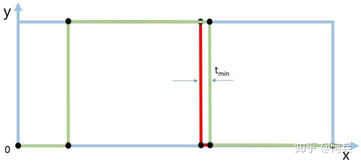
For example, in the double pulse test (DPT), when studying the current sharing problem of parallel power switch tubes, we need to control the driving signals of different switch tubes to arrive at different times, which involves the problem of the minimum timing interval between the two falling edges.

Figure 1 Minimum timing interval Tmin
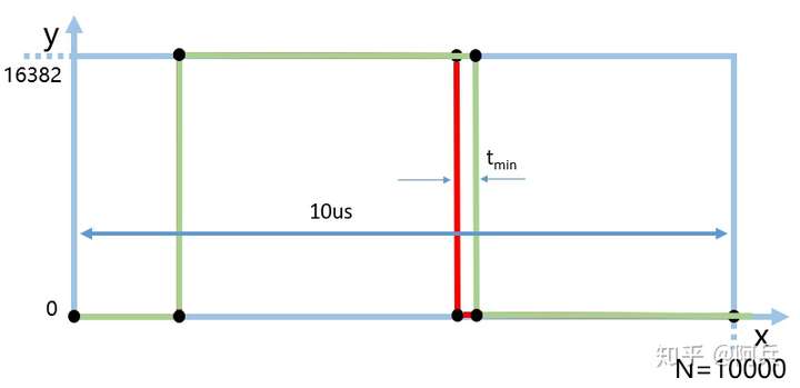
We use the "arbitrary wave" function of the Tektronix signal generator we talked about last week to test the minimum time interval between two waveforms. According to last week's article, we set the period to 10us and the number of horizontal axis points to N=10000 points.

Figure 2 Settings of the “Arbitrary Wave” interface
After a simple calculation, it can be found that under this setting, the difference between each point is 1ns.

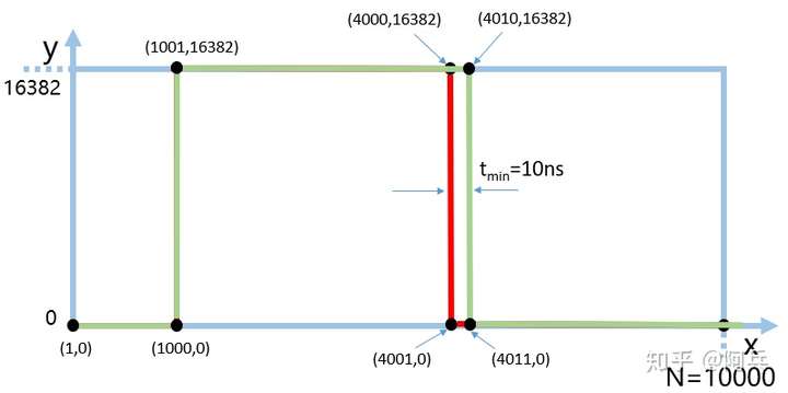
Figure 3 Coordinate setting with 10ns interval
We first set the falling edge difference of the two waveforms to ΔT = 10ns, and the coordinates are set as shown in Figure 3.
The output waveform observed using a 200MHz oscilloscope from Tektronix is shown in Figure 4.

Figure 4 Signal generator and the falling edge of the oscilloscope itself
As shown in Figure 4, the fall delay caused by the signal generator and the oscilloscope itself is 6.6ns.

Figure 5 The timing interval differs by 10ns
From Figure 5, we can see that when we set the difference between the two falling edges to 10ns, the actual waveform timing observed by the oscilloscope differs by 10.2ns, which is within the allowable error range and is accurate.
Similarly, we tested the limit case under 1ns, as shown in Figure 6.

Figure 6: Timing interval difference of 1ns
It can be found that when we set the timing difference between the two channel waveforms of the signal generator to 1ns, the oscilloscope observes that the actual output timing interval is about 1ns. It can be seen that using Tektronix's signal generator to set the dual-channel output timing interval to around 1ns is still relatively accurate.

Figure 7 Voltage overshoot caused by measurement method
Finally, it should be noted that, as can be observed from Figure 7, the voltage overshoot caused by the measurement method is relatively large, so when we test the circuit, we need to pay attention to the parasitic inductance of the test loop.
END
Previous article:How does the 0.35 coefficient of oscilloscope bandwidth and rise time come from?
Next article:How to set up a single channel dual pulse waveform using a Tektronix signal generator?
- Popular Resources
- Popular amplifiers
- New IsoVu™ Isolated Current Probes: Bringing a New Dimension to Current Measurements
- Modern manufacturing strategies drive continuous improvement in ICT online testing
- Methods for Correlation of Contact and Non-Contact Measurements
- Keysight Technologies Helps Samsung Electronics Successfully Validate FiRa® 2.0 Safe Distance Measurement Test Case
- From probes to power supplies, Tektronix is leading the way in comprehensive innovation in power electronics testing
- Seizing the Opportunities in the Chinese Application Market: NI's Challenges and Answers
- Tektronix Launches Breakthrough Power Measurement Tools to Accelerate Innovation as Global Electrification Accelerates
- Not all oscilloscopes are created equal: Why ADCs and low noise floor matter
- Enable TekHSI high-speed interface function to accelerate the remote transmission of waveform data
- Intel promotes AI with multi-dimensional efforts in technology, application, and ecology
- ChinaJoy Qualcomm Snapdragon Theme Pavilion takes you to experience the new changes in digital entertainment in the 5G era
- Infineon's latest generation IGBT technology platform enables precise control of speed and position
- Two test methods for LED lighting life
- Don't Let Lightning Induced Surges Scare You
- Application of brushless motor controller ML4425/4426
- Easy identification of LED power supply quality
- World's first integrated photovoltaic solar system completed in Israel
- Sliding window mean filter for avr microcontroller AD conversion
- What does call mean in the detailed explanation of ABB robot programming instructions?
- STMicroelectronics discloses its 2027-2028 financial model and path to achieve its 2030 goals
- 2024 China Automotive Charging and Battery Swapping Ecosystem Conference held in Taiyuan
- State-owned enterprises team up to invest in solid-state battery giant
- The evolution of electronic and electrical architecture is accelerating
- The first! National Automotive Chip Quality Inspection Center established
- BYD releases self-developed automotive chip using 4nm process, with a running score of up to 1.15 million
- GEODNET launches GEO-PULSE, a car GPS navigation device
- Should Chinese car companies develop their own high-computing chips?
- Infineon and Siemens combine embedded automotive software platform with microcontrollers to provide the necessary functions for next-generation SDVs
- Continental launches invisible biometric sensor display to monitor passengers' vital signs
- MSP430 MCU timer TA interrupt program
- Free review: Domestic FPGA Anlu SparkRoad development board
- Toshiba Photorelay Review - Getting to Know Photorelays
- Replaying MicroPython on STM32F7DISC - DCExpert
- CC4086------4-way 2-2-2 input AND-OR gate
- Wireless network technology and its application based on ZigBee
- Ask an expert about cpld
- Problems in PCB design
- Please share the installation package of modelsim10.4 or other versions
- ATE1133 audio decoding solution, USB sound card solution, TYPE C audio adapter chip solution

 Static Timing Analysis


 京公网安备 11010802033920号