If you need to measure a DUT with different reference impedances on each port, you must use the adapter removal/insertion characteristics and impedance conversion characteristics kit of the network analyzer. If the DUT is a two-port device with a characteristic impedance that can be converted from 50 Ω to 75 Ω, you must prepare a 50-75 Ω minimum loss pad and 50 Ω and 75 Ω calibration kits according to the connector type.
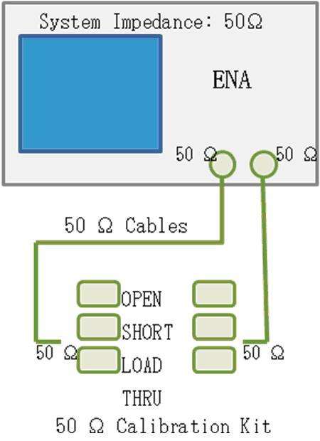
Step 1. Perform a full 2-port calibration using a 50 Ω calibration kit to calibrate the port where the adapter insertion/removal is performed (Figure 1).

Figure 1. Performing a full 2-port calibration using a 50 Ω calibration kit.
Step 2. Modify the 75 Ω calibration kit.
Select the desired 75 Ω calibration kit from Cal > Cal Kit.
Redefine the 75 Ω “Load” standard as “Arbitrary”.
Cal > Modify Cal Kit > Define STDs > Broadband > STD Type > Arbitrary

Step 3. Perform adapter insertion.
Open the Adapter Removal menu.
Cal > Calibrate > Adapter RemovalIn Select Port, select the port where you want to insert the minimum loss pad.
From Cal Kit, select the 75 Ω calibration kit (modified in step 2) that you want to use to characterize the minimum loss pad. Use the calibration kit on the flat surface where the adapter is inserted.
Connect the minimum loss pad to the selected test port.
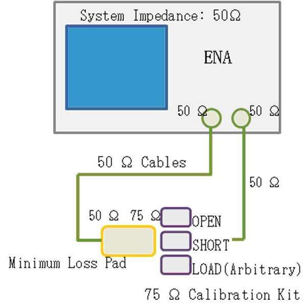
Connect the open, short and load of the 75 Ω calibration kit and click/press Open, Short and Load respectively (Figure 2). Use the ENA to measure the calibration kit standards, calculate the adapter characteristics and insert the adapter.
Click Done to complete the testing process.

Figure 2. Inserting the adapter using the 75 Ω calibration kit.
Note: Do not change the system characteristic impedance of ENA, which should be 50 Ω.

Step 4. Convert the reference impedance of the port connected to the minimum loss pad.
Open the Fixture Simulator menu.
Analysis > Fixture Simulator

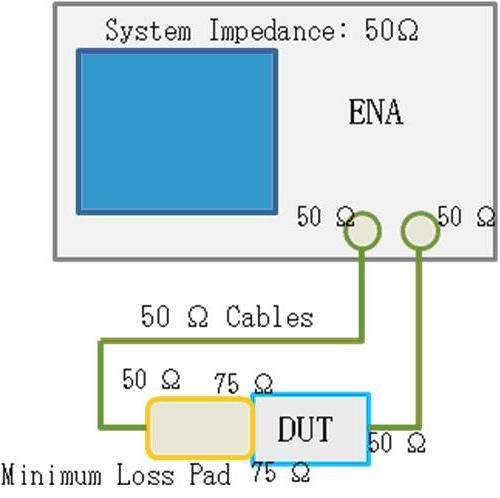
Figure 3. Measurement setup for 50-75 Ω impedance matching device.
Click Port Z Conversion and specify the reference impedance for the selected port. If the minimum loss pad is connected to Port 1, you need to change Port 1 Z0 Real from 50 Ω to 75 Ω.
Click Port Z Conversion to set the port impedance conversion function to ON.
Click Return.
Click Fixture Simulator and turn it ON.

Figure 4. Transition in reflection coefficient (S11) when connected to a 75 Ω load standard through an 11852B minimum loss pad.
Note: Because standard format files should be based on a reference impedance, when saving data in a standard format file, you must stop using the Port Z conversion and convert the port reference impedance back from 75 Ω to 50 Ω.
Previous article:How to solve the problem of output power level drop of vector network analyzer power supply?
Next article:Can I use the fixture simulator function of a 2-port network analyzer?
- Popular Resources
- Popular amplifiers
- New IsoVu™ Isolated Current Probes: Bringing a New Dimension to Current Measurements
- Modern manufacturing strategies drive continuous improvement in ICT online testing
- Methods for Correlation of Contact and Non-Contact Measurements
- Keysight Technologies Helps Samsung Electronics Successfully Validate FiRa® 2.0 Safe Distance Measurement Test Case
- From probes to power supplies, Tektronix is leading the way in comprehensive innovation in power electronics testing
- Seizing the Opportunities in the Chinese Application Market: NI's Challenges and Answers
- Tektronix Launches Breakthrough Power Measurement Tools to Accelerate Innovation as Global Electrification Accelerates
- Not all oscilloscopes are created equal: Why ADCs and low noise floor matter
- Enable TekHSI high-speed interface function to accelerate the remote transmission of waveform data
- Intel promotes AI with multi-dimensional efforts in technology, application, and ecology
- ChinaJoy Qualcomm Snapdragon Theme Pavilion takes you to experience the new changes in digital entertainment in the 5G era
- Infineon's latest generation IGBT technology platform enables precise control of speed and position
- Two test methods for LED lighting life
- Don't Let Lightning Induced Surges Scare You
- Application of brushless motor controller ML4425/4426
- Easy identification of LED power supply quality
- World's first integrated photovoltaic solar system completed in Israel
- Sliding window mean filter for avr microcontroller AD conversion
- What does call mean in the detailed explanation of ABB robot programming instructions?
- STMicroelectronics discloses its 2027-2028 financial model and path to achieve its 2030 goals
- 2024 China Automotive Charging and Battery Swapping Ecosystem Conference held in Taiyuan
- State-owned enterprises team up to invest in solid-state battery giant
- The evolution of electronic and electrical architecture is accelerating
- The first! National Automotive Chip Quality Inspection Center established
- BYD releases self-developed automotive chip using 4nm process, with a running score of up to 1.15 million
- GEODNET launches GEO-PULSE, a car GPS navigation device
- Should Chinese car companies develop their own high-computing chips?
- Infineon and Siemens combine embedded automotive software platform with microcontrollers to provide the necessary functions for next-generation SDVs
- Continental launches invisible biometric sensor display to monitor passengers' vital signs
- Power supply quality resource sharing, free points download this week
- 【Old Post 4】What is the best thing to use?
- Power amplifier circuit
- [NXP Rapid IoT Review] + Mobile Synchronizer 6
- Solution to the problem that the TI 280049 LaunchPad emulator cannot connect
- Voiceprint collection system based on Pingtouge RVB2601
- How to improve the execution efficiency of microcontroller programs?
- EEWORLD University Hall----Live playback: ADI voice interaction system solution
- Latest interpretation: What is Wi-Fi 7?
- Production of LCD Thermometer

 TC52N3733ECTRT


 京公网安备 11010802033920号