1. Digital multimeter is a powerful tool for electronic measurement. It can be used to measure the continuity of circuits in daily life. Multimeters are divided into digital multimeters and pointer multimeters. Generally, they are divided into voltage range (AC + DC), current range (AC + DC), and resistance range. The resistance range is used to measure continuity, which is the simplest function.
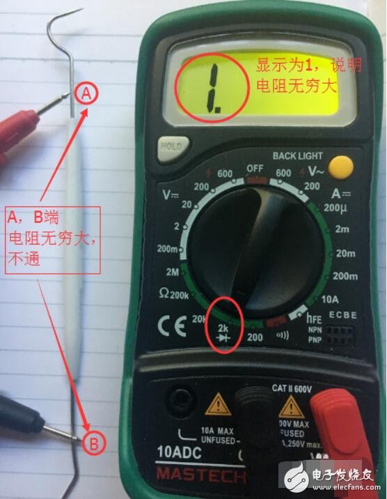
2. Let's take a dental probe as an example. The probe is a plastic handle with two metal needles connected, which is similar to our usual skinned wires. In order to determine whether point A and point B are conductive, we use the following steps:
1) First, make sure the wiring is correct. Insert the black wire into the COM port and the red wire into the V (omiga, or diode port)
2) Set the gear to 200 on the resistance scale, or the "buzzer, diode" scale.
3) Connect a red or black pen to the A and B terminals to be measured. If A and B are disconnected, the LCD screen will display "1", indicating infinite resistance.

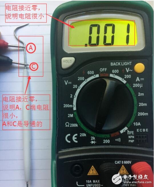
4) Use the same method to measure points A and C to determine whether they are connected. If the wire is connected, there will be a buzzer prompt sound, and the LCD screen will display a number close to "0", in this case it will display "0.001"; when using the resistance range, if the wire is connected, it will display a jumping number less than 200. The accuracy of the multimeter is different, and the measurement number is also different, but when it is connected, it will be a number close to zero.
The above method can be applied in daily life, such as measuring the continuity of wires, the on and off of electrical switches, etc.

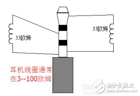
3. In daily life, there are other devices that can also be measured in this way, such as headphones and speakers, but their resistance will be slightly larger. The figure below is a schematic diagram of a headphone. You can see that there are two channels, left and right. In fact, the common end and the left and right channel ends are connected to a coil respectively, which vibrates and makes sound when powered on. The resistance of the coil is generally 30-100 ohms.

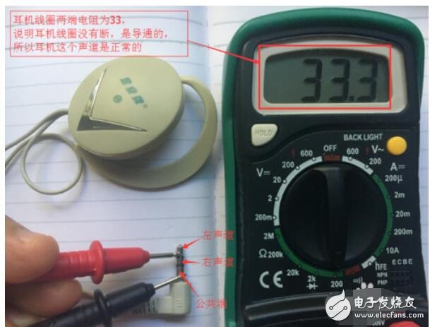
4. When measuring, you can connect the red and black test leads to the common terminal and the left and right channel terminals respectively. Be careful not to touch the wires between the red and black test leads. As shown in the example below, the resistance between the left channel and the common terminal is 33 ohms, indicating that this channel is normal. The same method can be used to judge the other channel.

5. For pointer multimeter:
1) Connect the red and black test leads correctly
2) Connect the red and black test leads to both ends of the line to be measured
3) If the pointer resistance is close to zero or relatively small, it means the line is connected. If it does not move or the resistance is very large, it means the line is disconnected.
Previous article:How to use a multimeter_ Tips on how to use a multimeter
Next article:Principle of digital multimeter measuring resistance_How to measure resistance with digital multimeter
- New IsoVu™ Isolated Current Probes: Bringing a New Dimension to Current Measurements
- Modern manufacturing strategies drive continuous improvement in ICT online testing
- Methods for Correlation of Contact and Non-Contact Measurements
- Keysight Technologies Helps Samsung Electronics Successfully Validate FiRa® 2.0 Safe Distance Measurement Test Case
- From probes to power supplies, Tektronix is leading the way in comprehensive innovation in power electronics testing
- Seizing the Opportunities in the Chinese Application Market: NI's Challenges and Answers
- Tektronix Launches Breakthrough Power Measurement Tools to Accelerate Innovation as Global Electrification Accelerates
- Not all oscilloscopes are created equal: Why ADCs and low noise floor matter
- Enable TekHSI high-speed interface function to accelerate the remote transmission of waveform data
- Intel promotes AI with multi-dimensional efforts in technology, application, and ecology
- ChinaJoy Qualcomm Snapdragon Theme Pavilion takes you to experience the new changes in digital entertainment in the 5G era
- Infineon's latest generation IGBT technology platform enables precise control of speed and position
- Two test methods for LED lighting life
- Don't Let Lightning Induced Surges Scare You
- Application of brushless motor controller ML4425/4426
- Easy identification of LED power supply quality
- World's first integrated photovoltaic solar system completed in Israel
- Sliding window mean filter for avr microcontroller AD conversion
- What does call mean in the detailed explanation of ABB robot programming instructions?
- STMicroelectronics discloses its 2027-2028 financial model and path to achieve its 2030 goals
- 2024 China Automotive Charging and Battery Swapping Ecosystem Conference held in Taiyuan
- State-owned enterprises team up to invest in solid-state battery giant
- The evolution of electronic and electrical architecture is accelerating
- The first! National Automotive Chip Quality Inspection Center established
- BYD releases self-developed automotive chip using 4nm process, with a running score of up to 1.15 million
- GEODNET launches GEO-PULSE, a car GPS navigation device
- Should Chinese car companies develop their own high-computing chips?
- Infineon and Siemens combine embedded automotive software platform with microcontrollers to provide the necessary functions for next-generation SDVs
- Continental launches invisible biometric sensor display to monitor passengers' vital signs
- Programmable analog circuit technology can significantly reduce the current power consumption of mobile phones by 10 to 100 times (Figure)
- Are there other ways to reduce heat and power consumption of MOS besides parallel connection? The current cannot be changed. Although the internal resistance can be...
- Multiple voltage output issues
- TI will broadcast [CAN SIC (Signal Improvement Function)] live at 10 am today. Learn the technology and win gifts!
- Can lemons generate electricity?
- [Repost] Popular Science of Components: The Structure and Application Prospects of MOSFET
- Free review | Anxinke Bluetooth development board PB-02-Kit
- Qinheng third generation USB to dual serial port chip CH342
- ASN.1 structure encoding rules related information
- Simulation and fabrication of low noise amplifier based on ADS

 Multisim Circuit System Design and Simulation Tutorial
 Design of diode characteristic tester based on 89C52


 京公网安备 11010802033920号