Digital inclinometer is a measuring tool for measuring small angles. It can be used to measure the inclination of the horizontal position, the parallelism and verticality of two parts, the straightness of machine tools and instrument guide rails, the flatness of the workbench, and the flatness of the plate, etc. It has a very broad application prospect. The
inclinometer in the design is an inclinometer based on thermal convection. The inclinometer has a small mass and generates a small inertial force under large impact or high overload. Therefore, it has a strong ability to resist vibration or impact. It is one of the few inclinometers that can have the advantages of simple structure, high reliability, and universal sensor integrated circuits. This design measures the inclination of the platform through the inclinometer, outputs a voltage signal, and after amplification by the operational amplifier, outputs it to the single-chip microcomputer circuit for data processing. Finally, the size of the inclination is displayed through the digital tube, and it can also be used as a control system to output a control signal to adjust the inclination of the platform.
1 Principle of digital inclinometer
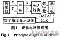
The overall hardware design principle of the inclinometer is shown in Figure 1. It consists of a sensor, a preamplifier circuit, an A/D conversion circuit, and a single-chip microcomputer system. The sensor collects acceleration information and outputs voltage values after internal conversion. The voltage values are divided into two paths, one for measuring the acceleration in the X-axis direction; the other for measuring the acceleration in the Y-axis direction. After low-pass filtering and amplification by the operational amplifier, the two voltage signals are output to the A/D conversion module. The A/D conversion module outputs 8-bit digital quantities to the single-chip microcomputer for processing. The single-chip microcomputer finally outputs serial data and outputs the tilt angle of the platform through the digital tube display circuit.
2 Working principle of sensor
The sensor used in the design is MXA2050A, which is a complete acceleration measurement system located on a single-chip integrated circuit CMOS IC. The sensor is based on natural convection for heat conduction. In MXA2050A, the gas is the only moving body in the sealed cavity. It has a small mass and generates small inertial force in large shocks or high overloads. Therefore, it has strong resistance to vibration or shock. It is an extremely low-cost dual-axis accelerometer. Because it has no moving parts, the device is particularly reliable. Moreover, it can be manufactured based on a sub-micron CMOS method. This method can produce small-sized chips, so this device is very cheap and versatile. The MXA2050A acceleration measurement range is: ±10gn, and the output is two analog voltage signals. It allows resolution of less than 10 mg in a 1 Hz bandwidth. The frequency response can be extended to 40Hz. With a simple external circuit, the frequency response is extended to 160Hz. The
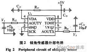
thermal convection accelerometer contains a closed cavity filled with fluid. There is a heating element that heats the fluid around the heating element in the cavity. The heated fluid expands and the density decreases. It rises under the action of gravity, and the surrounding relatively cold fluid replenishes the empty position. In this way, repeated cycles cause heat convection conduction. In the static state, the temperature curve is symmetrical. In the case of acceleration, due to natural convection heat conduction, acceleration in any direction will disturb the temperature and cause temperature asymmetry. Therefore, the temperature and output voltage of the four thermopiles in the accelerometer are different. The output voltage of different thermopiles is directly proportional to the acceleration. The accelerometer has two identical acceleration signal channels. One is to measure the acceleration in the X-axis direction; the other is to measure the acceleration in the Y-axis direction. The peripheral circuit is shown in Figure 2.
3 Operational amplifier, A/D conversion and display circuit
In the application of sensors, the high-impedance preamplifier has two main functions: one is to amplify the weak signal of the sensor; the other is to convert the high-impedance output of the sensor into a low-impedance output. The preamplifier in the design is mainly composed of the AD623 amplifier circuit, and the circuit diagram is shown in Figure 3. The
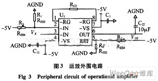
operational amplifier AD623 can realize the functions of subtraction, addition, and amplification at the same time. The signal VX output by the sensor is first subtracted from its zero voltage in the horizontal direction, and then amplified by G times, and then added with the reference voltage VREF. The final output is the

Amplification factor can be adjusted by adjusting the size of RG1. The reference voltage is output by the sliding rheostat. The voltage signal generated by the sensor is first output to the A/D conversion circuit after passing through the amplifier. The A/D conversion uses TLC5510, which can realize the speed of conversion controlled by the single-chip microcomputer. The output digital quantity is 8 bits, which can achieve the accuracy requirements of the design. [page]
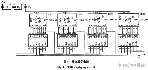
The display circuit is mainly composed of two parts: shift register and digital tube display. The data processed by the single-chip microcomputer is converted into serial format data. Under the action of the clock signal, the shift display is realized through the shift register. The display circuit uses a total of 8 shift registers and 8 digital tubes to realize the 4-bit angle display in the x and y directions respectively, with an accuracy of 0.01°. The shift display circuit is shown in Figure 4.
4 Experimental results and data processing
In the process of experimental data processing, multiple groups of data are measured and their arithmetic mean is calculated as the final measured result. Therefore, it is necessary to study the uncertainty determination criteria of the arithmetic mean. If multiple groups of repeated series of measurements are made on the same value under the same conditions, each series of measurements has an arithmetic mean. Due to the existence of random errors, the arithmetic mean of each measurement column is also different. They have a certain dispersion around the true value of the measured value. This dispersion explains the uncertainty of the arithmetic mean, and the standard deviation σ of the arithmetic mean is a parameter that characterizes the dispersion of the arithmetic mean of each independent measurement column of the same measured value, which can be used as the determination standard of the uncertainty of the arithmetic mean. It is known that the arithmetic mean x is

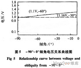
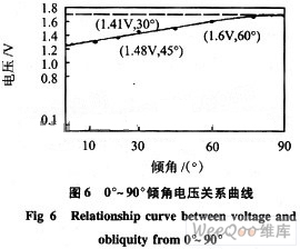
From this, it can be seen that in the equal-precision measurement series of n measurements, the standard deviation of the arithmetic mean is the standard deviation of a single measurement. When the number of measurements n is larger, the arithmetic mean is closer to the true value of the measurement, and the measurement accuracy is higher. Increasing the number of measurements can improve the measurement accuracy. However, it can be seen from the above formula that the measurement accuracy is inversely proportional to the square root of the number of measurements. Therefore, to significantly improve the measurement accuracy, a lot of work must be done. Practice also shows that after n>10, σ-x has decreased very slowly. In addition, since the larger the number of measurements, the more difficult it is to ensure the constant measurement conditions, which may introduce new errors. Generally, n=10 is taken. Therefore, in the experiment, the arithmetic mean of the measurement results of 10 times is taken as the final measurement result. The voltage inclination relationship curves drawn after measurement are shown in Figures 5 and 6.
5 Conclusion
In order to meet the market demand of machinery manufacturing, equipment installation, road and bridge, construction engineering and other industries and exports, a digital display inclinometer based on acceleration sensor is designed, with a resolution of 0.01° and a comprehensive accuracy of 0.03°, reaching the level of similar products at home and abroad; it has high cost performance. It is widely used in surveying and mapping instruments, construction machinery, antenna positioning, robotics, tank and ship artillery platform control, aircraft attitude, automotive electronic control, oil exploration, offshore platform monitoring, etc.
Reference address:Design of Digital Inclinometer
inclinometer in the design is an inclinometer based on thermal convection. The inclinometer has a small mass and generates a small inertial force under large impact or high overload. Therefore, it has a strong ability to resist vibration or impact. It is one of the few inclinometers that can have the advantages of simple structure, high reliability, and universal sensor integrated circuits. This design measures the inclination of the platform through the inclinometer, outputs a voltage signal, and after amplification by the operational amplifier, outputs it to the single-chip microcomputer circuit for data processing. Finally, the size of the inclination is displayed through the digital tube, and it can also be used as a control system to output a control signal to adjust the inclination of the platform.
1 Principle of digital inclinometer
The overall hardware design principle of the inclinometer is shown in Figure 1. It consists of a sensor, a preamplifier circuit, an A/D conversion circuit, and a single-chip microcomputer system. The sensor collects acceleration information and outputs voltage values after internal conversion. The voltage values are divided into two paths, one for measuring the acceleration in the X-axis direction; the other for measuring the acceleration in the Y-axis direction. After low-pass filtering and amplification by the operational amplifier, the two voltage signals are output to the A/D conversion module. The A/D conversion module outputs 8-bit digital quantities to the single-chip microcomputer for processing. The single-chip microcomputer finally outputs serial data and outputs the tilt angle of the platform through the digital tube display circuit.

2 Working principle of sensor
The sensor used in the design is MXA2050A, which is a complete acceleration measurement system located on a single-chip integrated circuit CMOS IC. The sensor is based on natural convection for heat conduction. In MXA2050A, the gas is the only moving body in the sealed cavity. It has a small mass and generates small inertial force in large shocks or high overloads. Therefore, it has strong resistance to vibration or shock. It is an extremely low-cost dual-axis accelerometer. Because it has no moving parts, the device is particularly reliable. Moreover, it can be manufactured based on a sub-micron CMOS method. This method can produce small-sized chips, so this device is very cheap and versatile. The MXA2050A acceleration measurement range is: ±10gn, and the output is two analog voltage signals. It allows resolution of less than 10 mg in a 1 Hz bandwidth. The frequency response can be extended to 40Hz. With a simple external circuit, the frequency response is extended to 160Hz. The
thermal convection accelerometer contains a closed cavity filled with fluid. There is a heating element that heats the fluid around the heating element in the cavity. The heated fluid expands and the density decreases. It rises under the action of gravity, and the surrounding relatively cold fluid replenishes the empty position. In this way, repeated cycles cause heat convection conduction. In the static state, the temperature curve is symmetrical. In the case of acceleration, due to natural convection heat conduction, acceleration in any direction will disturb the temperature and cause temperature asymmetry. Therefore, the temperature and output voltage of the four thermopiles in the accelerometer are different. The output voltage of different thermopiles is directly proportional to the acceleration. The accelerometer has two identical acceleration signal channels. One is to measure the acceleration in the X-axis direction; the other is to measure the acceleration in the Y-axis direction. The peripheral circuit is shown in Figure 2.

3 Operational amplifier, A/D conversion and display circuit
In the application of sensors, the high-impedance preamplifier has two main functions: one is to amplify the weak signal of the sensor; the other is to convert the high-impedance output of the sensor into a low-impedance output. The preamplifier in the design is mainly composed of the AD623 amplifier circuit, and the circuit diagram is shown in Figure 3. The

operational amplifier AD623 can realize the functions of subtraction, addition, and amplification at the same time. The signal VX output by the sensor is first subtracted from its zero voltage in the horizontal direction, and then amplified by G times, and then added with the reference voltage VREF. The final output is the

Amplification factor can be adjusted by adjusting the size of RG1. The reference voltage is output by the sliding rheostat. The voltage signal generated by the sensor is first output to the A/D conversion circuit after passing through the amplifier. The A/D conversion uses TLC5510, which can realize the speed of conversion controlled by the single-chip microcomputer. The output digital quantity is 8 bits, which can achieve the accuracy requirements of the design. [page]
The display circuit is mainly composed of two parts: shift register and digital tube display. The data processed by the single-chip microcomputer is converted into serial format data. Under the action of the clock signal, the shift display is realized through the shift register. The display circuit uses a total of 8 shift registers and 8 digital tubes to realize the 4-bit angle display in the x and y directions respectively, with an accuracy of 0.01°. The shift display circuit is shown in Figure 4.

4 Experimental results and data processing
In the process of experimental data processing, multiple groups of data are measured and their arithmetic mean is calculated as the final measured result. Therefore, it is necessary to study the uncertainty determination criteria of the arithmetic mean. If multiple groups of repeated series of measurements are made on the same value under the same conditions, each series of measurements has an arithmetic mean. Due to the existence of random errors, the arithmetic mean of each measurement column is also different. They have a certain dispersion around the true value of the measured value. This dispersion explains the uncertainty of the arithmetic mean, and the standard deviation σ of the arithmetic mean is a parameter that characterizes the dispersion of the arithmetic mean of each independent measurement column of the same measured value, which can be used as the determination standard of the uncertainty of the arithmetic mean. It is known that the arithmetic mean x is

From this, it can be seen that in the equal-precision measurement series of n measurements, the standard deviation of the arithmetic mean is the standard deviation of a single measurement. When the number of measurements n is larger, the arithmetic mean is closer to the true value of the measurement, and the measurement accuracy is higher. Increasing the number of measurements can improve the measurement accuracy. However, it can be seen from the above formula that the measurement accuracy is inversely proportional to the square root of the number of measurements. Therefore, to significantly improve the measurement accuracy, a lot of work must be done. Practice also shows that after n>10, σ-x has decreased very slowly. In addition, since the larger the number of measurements, the more difficult it is to ensure the constant measurement conditions, which may introduce new errors. Generally, n=10 is taken. Therefore, in the experiment, the arithmetic mean of the measurement results of 10 times is taken as the final measurement result. The voltage inclination relationship curves drawn after measurement are shown in Figures 5 and 6.


5 Conclusion
In order to meet the market demand of machinery manufacturing, equipment installation, road and bridge, construction engineering and other industries and exports, a digital display inclinometer based on acceleration sensor is designed, with a resolution of 0.01° and a comprehensive accuracy of 0.03°, reaching the level of similar products at home and abroad; it has high cost performance. It is widely used in surveying and mapping instruments, construction machinery, antenna positioning, robotics, tank and ship artillery platform control, aircraft attitude, automotive electronic control, oil exploration, offshore platform monitoring, etc.
Previous article:Design of Caller ID Phone Tester Based on CMX860
Next article:Design of portable voice environment parameter tester
Recommended ReadingLatest update time:2024-11-16 04:12
New sensor could help tell if meat or fish has gone bad
According to a report on the website of German weekly Der Spiegel on June 5, nearly one-third of the world's food is thrown into the garbage dump. The average German throws away 55 kilograms of fruit, vegetables, bread and meat every year. This is not only a waste of food, but also has an adverse impact on the env
[sensor]
Secondary instrument design of flow meter based on vortex flow sensor AT89C51/LV51 microcontroller

1 Introduction With the continuous improvement of the automation level of modern industry, in many cases it is necessary to monitor multiple flow points intensively. For example, in the process of oil water injection extraction, in order to maintain the mining effect, protect the underground environment and subsequent
[Microcontroller]

Teledyne e2v releases new generation of high-performance global shutter CMOS image sensor

Emerald Gen2 is ideal for ultra-fast, sharp imaging applications Grenoble, France, November 21, 2023 - Teledyne e2v, a subsidiary of Teledyne Technologies and a global innovator in imaging solutions, has launched a new high-level CMOS image sensor series Emerald™ Gen2. The new series builds on Teledyne e2v's advance
[sensor]

How to measure the quality of 2-wire temperature sensor
The 2-wire temperature sensor is a common temperature measurement device, which is widely used in industry, scientific research, medical treatment and other fields. This article will introduce in detail the working principle, performance indicators, measurement methods and how to judge whether the 2-wire temperature
[Test Measurement]
The security market is considering replacing infrared with radar sensors

This article was written by Niel Smith, Socionext America Inc. Home security devices are very popular nowadays as they provide an extra layer of security to a home or office. They are easy to install and are inexpensive. Many popular home security devices utilize PIR (Pyrotechnic Infrared Sensor) as a motion detecti
[Security Electronics]

The market demand for automotive sensors is increasing

The market demand for automotive sensors is increasing
Automotive safety is a major challenge facing designers, especially today, when consumers define safety not only as the safety and reliability of the vehicle itself, but also as assisted driving systems that can provide more safety protection through electronic
[Analog Electronics]

Infineon Technologies and SensiML collaborate to deliver sensor data for smart home, fitness and industrial applications
Infineon Technologies and SensiML collaborate to provide sensor data and train machine learning models for smart home, fitness and industrial applications Infineon Technologies AG is working with SensiML to provide developers with the SensiML Analytics Toolkit development software and ModusToolbox™ suite so that th
[Internet of Things]
ZF and Aeva team up to develop new autonomous driving sensors

Recently, foreign media learned that ZF and Silicon Valley startup Aeva will jointly develop a new self-driving car sensor (LiDAR), which uses frequency modulated continuous wave (FMCW) technology to detect the speed of distant objects and distinguish between stationary (such as trees) and moving objects (such as bicy
[Automotive Electronics]

- Popular Resources
- Popular amplifiers
-
 Analysis and Implementation of MAC Protocol for Wireless Sensor Networks (by Yang Zhijun, Xie Xianjie, and Ding Hongwei)
 -
 Introduction to Internet of Things Engineering 2nd Edition (Gongyi Wu)
 -
 西门子S7-12001500 PLC SCL语言编程从入门到精通 (北岛李工)
 -
 Modern Motor Control Technology (Wang Chengyuan, Xia Jiakuan, Sun Yibiao)
Recommended Content
Latest Test Measurement Articles
- Keysight Technologies Helps Samsung Electronics Successfully Validate FiRa® 2.0 Safe Distance Measurement Test Case
- From probes to power supplies, Tektronix is leading the way in comprehensive innovation in power electronics testing
- Seizing the Opportunities in the Chinese Application Market: NI's Challenges and Answers
- Tektronix Launches Breakthrough Power Measurement Tools to Accelerate Innovation as Global Electrification Accelerates
- Not all oscilloscopes are created equal: Why ADCs and low noise floor matter
- Enable TekHSI high-speed interface function to accelerate the remote transmission of waveform data
- How to measure the quality of soft start thyristor
- How to use a multimeter to judge whether a soft starter is good or bad
- What are the advantages and disadvantages of non-contact temperature sensors?
MoreSelected Circuit Diagrams
MorePopular Articles
- LED chemical incompatibility test to see which chemicals LEDs can be used with
- Application of ARM9 hardware coprocessor on WinCE embedded motherboard
- What are the key points for selecting rotor flowmeter?
- LM317 high power charger circuit
- A brief analysis of Embest's application and development of embedded medical devices
- Single-phase RC protection circuit
- stm32 PVD programmable voltage monitor
- Introduction and measurement of edge trigger and level trigger of 51 single chip microcomputer
- Improved design of Linux system software shell protection technology
- What to do if the ABB robot protection device stops
MoreDaily News
- Allegro MicroSystems Introduces Advanced Magnetic and Inductive Position Sensing Solutions at Electronica 2024
- Car key in the left hand, liveness detection radar in the right hand, UWB is imperative for cars!
- After a decade of rapid development, domestic CIS has entered the market
- Aegis Dagger Battery + Thor EM-i Super Hybrid, Geely New Energy has thrown out two "king bombs"
- A brief discussion on functional safety - fault, error, and failure
- In the smart car 2.0 cycle, these core industry chains are facing major opportunities!
- The United States and Japan are developing new batteries. CATL faces challenges? How should China's new energy battery industry respond?
- Murata launches high-precision 6-axis inertial sensor for automobiles
- Ford patents pre-charge alarm to help save costs and respond to emergencies
- New real-time microcontroller system from Texas Instruments enables smarter processing in automotive and industrial applications
Guess you like
- Problems with STM32F4 serial port 4 standard library program
- 【FAQ】Microchip Live|Wireless Power Consortium (WPC) compliant wireless charging authentication
- Recruiting part-time dsp training instructors
- Software platform installation for SILICON LABS PG22-DK2503A development board
- [ADI Practical Knowledge Sharing] The hidden costs of isolation system design cannot be ignored!
- EEWORLD University - Amplifier Design in Test and Measurement
- Design and implementation of FM function in handheld devices
- TI mmWave Radar China Tour
- What is the io write speed of R16 itself?
- MSP430G2553 electronic clock experiment

 Analysis and Implementation of MAC Protocol for Wireless Sensor Networks (by Yang Zhijun, Xie Xianjie, and Ding Hongwei)


 京公网安备 11010802033920号