Detailed explanation of CAN and CANopen protocol stack [Hardcore, click carefully]
Chapter 1 Detailed Explanation of CAN Protocol Stack
In this chapter
-
Preface
-
1. Introduction to CAN
-
2. Development History of CAN
-
3. Electrical characteristics of CAN
-
4. CAN Protocol Stack
-
4.1、CAN protocol stack analysis
-
4.2 CAN sending and receiving process
-
4.3 CAN error handling
-
4.4 CAN baud rate
-
4.5 CAN Filtering
-
Summarize
This chapter introduces the development history, electrical characteristics, basic theories, standard protocol stack analysis and other key knowledge points of the CAN protocol stack.
1. Introduction to CAN
CAN consists of two parts, namely CAN bus and CAN bus protocol.
CAN bus:
CAN bus protocol:
-
CSMA: It means that every node on the bus must monitor the bus before attempting to send a message, and can only send when the bus is idle.
-
CD+AMP: means that collisions are resolved by pre-programmed message priority bit by bit arbitration, and the message priority is located in the identification field of each message. The message with a higher priority identifier always gets bus access, that is, the last one in the identifier that remains at a logic high level will continue to transmit because it has a higher priority.
2. Development History of CAN
-
In the early 1980s, because there was no bus protocol that satisfied automotive engineers, people began to develop new serial buses.
-
In February 1986, the CAN bus was born at the SAE meeting held in Detroit and was called Automotive Serial Controller Area Network.
-
In 1991, Bosch released the CAN2.0 specification, which was divided into CAN 2.0A (with an 11-bit identifier) and CAN 2.0B (with a 29-bit identifier).
-
In 1993, the ISO organization released the CAN standard IS0 11898: IS0 11898-1 covers the data link layer, IS0 11898-2 covers the CAN physical layer of high-speed CAN (classic CAN speed 1Mbps, CAN FD 5Mbps), IS0 11898-3 covers the physical layer of low-speed, fault-tolerant CAN (speed 125Kbps), and ISO 11898-4 -5 and -6 standards were subsequently launched.
-
In 2012, Bosch released CAN FD 1.0 with a speed of 2Mbps. Using CAN FD-SiC (enhanced CAN PHY), it can achieve 5-8Msps. Taking STM32H7 as an example, the CANFD it carries supports CAN2.0A and CAN2.0B of classic CAN, as well as CANFD V1.0 specification, and is compatible with ISO 11898-1: 2015 and ISO11898-4.
-
In December 2018, the third-generation CAN data link layer protocol CAN XL was launched, with the speed increased to 10Mbsp.
-
In November 2022, Bosch launched the next-generation CAN IP core CAN XL with a speed of up to 20Mbps.
3. Electrical characteristics of CAN
-
During the CAN bus test phase, the 120Ω terminal resistor at at least one end cannot be omitted.

-
CAN is a differential communication, and the bus level is divided into two types: dominant level and recessive level. The bus performs a logical "AND": the dominant level is 0, and the recessive level is 1. The dominant level is dominant, and the bus is recessive only when all nodes output the recessive level.

-
The measurement found that when CAN is connected to the terminal resistance at only one end, the waveform will be raised at the end.
-
Theoretical values of communication speed and maximum length, mainly for classic CAN, all nodes must operate at the same CAN baud rate.
-
During the testing phase, when testing the software application layer, since most STM32 chips are dual CAN, CAN communication can be achieved without using a CAN PHY chip through special operations, but this is not a differential level.

4. CAN Protocol Stack
The frame types of the CAN protocol stack include data frame, remote frame, error frame, overload frame and frame interval.
4.1、CAN protocol stack analysis
-
Data frame : A frame that transmits data from a sending unit to a receiving unit.

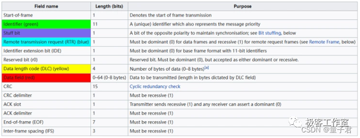
①Starting segment: indicates the segment where the data frame starts.
SOF: Start of Frame (1 bit), dominant (0) indicates the beginning of a message and is used to synchronize nodes on the bus.
②Arbitration segment: The segment indicating the priority of the frame.Identifier: Identifier (11 bits), the standard format has an 11-bit identifier, which is used to determine the priority of the message. The smaller the value of this field, the higher the priority.
RTR: Remote Transmit Request bit (1 bit), this bit is dominant (0) when information needs to be requested from another node (remote control frame).
All nodes can receive this request, but the frame identifier identifies the intended node. The response data frame is also received by all nodes and can be used by interested nodes.
③Control segment: A segment indicating the number of bytes of data and reserved bits.IDE: extension bit (1 bit) of the identifier. When it is dominant (0), the standard format is used. When it is recessive (1), it indicates that this is the extended format.
r0: Reserved bit (1 bit), all must be sent at dominant level, but the receiver can receive any level.
DLC: Data length code (4 bits), indicating the number of bytes of transmitted data. A frame can transmit up to 8 bytes of user data.
④Data segment: data content, classic CAN supports 0-8 bytes, and CANFD supports 0-64 bytes.⑤ Check segment: The segment that checks the transmission errors of the frame.
CRC: Classic CAN uses a 15-bit + 1-bit CRC delimiter (for bit separation), and CAN FD uses a 17 or 21-bit + 1 delimiter.
CRC Delimiter: Set to “1”.
The calculation scope of CRC includes the start segment, arbitration segment, control segment, and data segment. The receiver calculates the CRC value using the same algorithm and compares them. If they are inconsistent, an error will be reported.
⑥ Response segment: indicates the segment confirming normal reception.ACK: Contains the acknowledge bit and the acknowledge delimiter (2 bits).
In the message frame of the sending node, the two ACK bits are recessive bits. When the receiver correctly receives a valid message, the receiver will send a dominant bit to the sending node during the ACK bit period to indicate an ACK.
If the receiver finds that there is an error in this frame of data, it will not send an ACK response to the sending node, and the sending node will retransmit the frame of data later.
⑦ End segment: indicates the end of the data frame.EOF: End of frame flag (7 bits), all recessive bits. If a dominant bit appears in these 7 bits, a stuffing error will occur.
IFS: Frame Interval Flag (7 bits). It takes a certain amount of time for the CAN controller to correctly put the received frame into the message buffer. The frame interval can provide this time.
-
Remote frame: A frame in which a receiving unit requests data from a sending unit with the same ID.
Remote control is used for frames where the receiving unit requests data from the sending unit with the same ID. CANFD does not have remote control frames, only classic CAN has remote frames. Compared with data frames, remote frames do not have data segments. It should be noted that the official CAN recommendation is no longer to use remote frames.
The extended format has the following changes compared to the standard format:
①SRR: replaces the remote request bit, which is recessive. Therefore, when the standard frame and the extended frame conflict with each other and the basic identifier of the extended frame is the same as the identifier of the standard frame, the standard frame has a higher priority than the extended frame.②IDE: It is a recessive bit indicating the flag bit extended frame, and the 18-bit extended identifier follows the IDE bit.③18-bit identifier: Add an 18-bit identifier.④r1: reserved bit. -
Error frame: A frame that notifies other units of an error when an error is detected.
When a receiving node or a sending node detects an error, it notifies the error frame.
Active error flag: 6 bits of dominant bit;Passive error flag: 6 bits of recessive bits;Error delimiter: 8 bits recessive. -
Overload frame: A frame in which the receiving unit indicates that it is not yet ready.
-
Interframe interval: A frame that separates data frames and remote control frames from the previous frame.
4.2 CAN sending and receiving process
-
Sending process
① Set the ID, DLC, data, etc. of the sending node.
② Set up the CAN controller and start sending frames.
③ Any node can start sending frames when the bus is idle.
④ Except for the node that starts sending data, all other nodes are waiting to receive data.
⑤ If multiple nodes start sending data at the same time, arbitration will be performed, and the node with a smaller ID value will be processed first, while the node with a larger ID value will stop sending and enter the receiving state.
⑥ At this time, only one node sends data, otherwise other nodes sending data will cause abnormalities.
⑦ When the sending node completes sending the message, it will wait for the response bit to be pulled down to 0, indicating that the receiving node has received the data normally.
⑧ The data of the sending node has been delivered to the receiving node, and the sending node continues to send the end segment of the frame data. After that, the sending node will enter the receiving state or continue to send the next frame of data. The receiving node will process the received data.
⑨ At this time, any node can send data. If no node sends data, the bus will enter an idle state.
⑩ If no response is received, it will be processed as a CAN error.
-
Receiving process
① All nodes, except nodes sending data and nodes in bus-off state, are in listening state.
② CAN data will be sent according to the CAN sending process mentioned above.
③ All nodes in the listening state will receive the data, and if it is considered to be a valid CAN message without errors, the listening node will respond.
④ If the receiving node has a CAN filter set, unnecessary messages will be filtered out according to the filter settings.
4.3 CAN error handling
Detected framing error handling:

-
A node receiving an error will pull the bus low (dominant level 0) for at least 6 bits.
-
If more than 5 bits have the same polarity, bit filling will be triggered. This is done by hardware and does not require user operation.
-
Error frames are sent to all nodes as notifications, which is done by hardware.
-
The transmitting bus abandons the current frame and the value of the 8-bit TEC transmit error counter register is increased by X.
-
If this TEC equals 0xFF, the sending node will BUSOFF (bus off) and remove itself from the bus.
-
If not, an attempt is made to retransmit the message, which must be prioritized again along with the other messages.
-
All other nodes give up reading the current frame, and the value of the REC receive error counter register is increased by X.
-
Any nodes that had messages queued will now start sending them, and other nodes will listen.
-
Each time a frame is transmitted or received successfully, the corresponding TEC and REC registers are decremented (usually only by 1).
4.4 CAN baud rate
CANFD baud rate calculation includes variable baud rate in arbitration phase and variable baud rate in data phase, while classic CAN has only one baud rate.
4.5 CAN Filtering
The identifier filter is used for receiving. There is no need to set a filter when sending. According to the frame data sent by the sender, the identifier filter can be set to receive only the frame data that needs to be received, effectively reducing the redundant CPU processing time.
-
Classical CAN supports identifier list mode and mask bit mode.
-
CANFD supports range filters, filters for dedicated IDs and classic bit mask filters.
Summarize
This chapter introduces the development history, electrical characteristics, basic theory, standard protocol stack analysis and other key knowledge points of the CAN protocol stack.
In this chapter
-
Preface
-
1. Introduction to CANopen
-
2. Development History of CANopen
-
3. CANopen ID
-
4. CANopen protocol stack framework
-
5. PDO
-
6. SDO
-
6.1 Fast SDO message format:
-
6.2. Ordinary SDO message format:
-
6.2.1 Common SDO read operation message format
-
6.2.2 Common SDO write operation message format
-
7. NMT
-
8. Timestamp Protocol
-
9. Synchronization Protocol
-
10. Emergency Message Protocol
-
Summarize
1. Introduction to CANopen
-
The message transmission adopts the CAN standard frame format, that is, the 11- bit ID field, to minimize the transmission time;
-
Network control messages all use the minimum number of bytes of data. For example, a heartbeat message only has 1 byte of data;
-
The real-time updated process data does not require the receiver to reply to the message, that is, the production and consumption model is adopted to reduce the bus load;
-
Configuration parameters that require confirmation by the receiver are generally transmitted using fast single-word transmission, that is, one message transmits a maximum of one 32- bit parameter variable to avoid the reduction of real-time performance caused by framing.
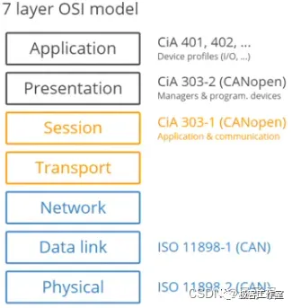
From the perspective of OSI's 7- layer network model , CAN (Controller Area Network) fieldbus only defines Layer 1 (physical layer, see ISO11898-2 standard) and Layer 2 (data link layer, see ISO11898-1 standard); in actual design, these two layers are completely implemented by hardware, and designers no longer need to develop related software (Software) or firmware (Firmware) for this purpose. As long as they understand how to call related interfaces and registers, they can complete the control of CAN.
-
Application layer: provides a set of useful services and protocols for every valid device in the network.
-
Communication profile: Provides the meaning of configuration equipment and communication data, and defines the data communication method.
-
Device proflile: Add standardized behaviors to devices (classes) .
2. Development History of CANopen
-
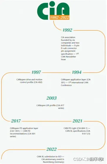
In 1994, the CiA Alliance (CAN in Automation) released the first version of CANopen, CiA301. The success of CANopen was not driven by a large supplier, but by many small and medium-sized enterprises.
-
In the early days of CANopen, CAN remote was still popular, and node protection was also designed based on remote frames, which were later replaced by heartbeat messages. The current CiA specification no longer recommends the use of remote frames.
-
CiA301 is the most important basic protocol of CANopen. The first version has defined PDO (Process Data Object) and SDO (Service Data Object), introduced synchronous transmission of PDO, network management (NMT) and emergency messages. Later, based on CiA301, a large number of sub-protocols were launched for various industries.
3. CANopen ID
-
The CAN-ID here is also called COB-ID (Communication Objectldentifier).
-
Node-ID: Node ID, up to 128, ranging from 0 to 127.


4. CANopen protocol stack framework

5. PDO
-
PDO Introduction:
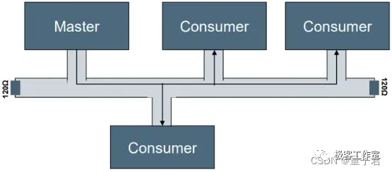
Process data, i.e. one-way transmission, does not require the receiving node to respond to the CAN message for confirmation. In terms of communication terms, it is a "production and consumption" model, and the data length is limited to 1 to 8 bytes. A maximum of 1 is needed to complete the transmission of a message or a variable.
-
PDO protocol:
The node's PDO defines a total of 8 data objects, 4 for TPDO and 4 for RPDO, as shown in the following figure:
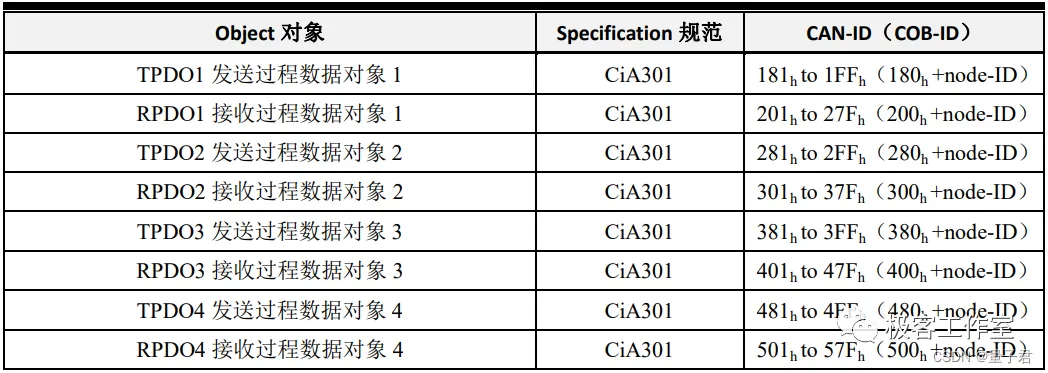
PDO data objects have three important parameters, namely communication parameters, mapping parameters, and data storage. RPDO communication parameters are 1400h to 15FFh, mapping parameters are 1600h to 17FFh, and data is stored in the manufacturer-defined area after 2000h: TPDO communication parameters are 1800h to 19FFh, mapping parameters are 1A00h to 1BFFh, and data is stored in the manufacturer-defined area after 2000h. All PDO transmission data must be mapped to the corresponding index area through the object dictionary.
-
PDO communication parameters:
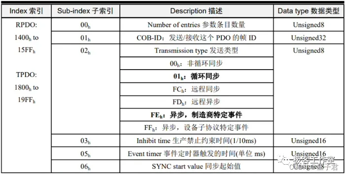
①Number of entries: the number of parameters in this index;②COB-ID: the corresponding CAN ID sent or received by this PDO;③ Send type: the transmission form of this PDO sending or receiving, usually using cyclic synchronous and asynchronous manufacturer-specific events;④Inhibit time (1/10ms): It constrains the minimum interval of PDO sending to avoid a sharp increase in bus load. For example, if the digital input is too fast, the TPDO sent for state change will be frequently sent, which will increase the bus load. Therefore, a constraint time is needed for "filtering". The time unit is 0.lms.⑤Event timer Event timer trigger time (unit: ms): If the timing time of a PDO sent at a fixed time is 0, the PDO is sent for event change;⑥SYNC start value: The synchronous transmission PDO will be sent after receiving a certain number of synchronization packets. This synchronization start value is the number of synchronization packets. For example, if it is set to 2, it will be sent after receiving 2 synchronization packets.
-
PDO Mapping:

6. SDO
-
SDO Introduction:
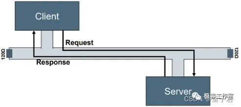
Service data is mainly used for the CANopen master to configure the parameters of the slave node. A response is generated for each message to ensure the accuracy of data transmission. In a CANopen system, the CANopen slave node usually acts as the SDO server and the CANopen master node acts as the client.
-
SDO protocol:
SDO is divided into fast SDO protocol and ordinary SDO protocol. The maximum length of fast SDO data is 4 bytes, and there is no maximum limit for ordinary SDO. Its message format is shown in the figure below, which consists of command code, index, sub-index and data.

The SDO definition of the node is shown in the following figure:

The SDO client can access the object dictionary on the SDO server through indexes and sub-indexes. In this way, the CANopen master node can access the parameters of any object dictionary item of the slave node, and SDO can also transmit data of any length. The sender (client) sends a message with CAN-ID of 600h+Node-ID, Node-D is the node address of the receiver (server), and the data length is 8 bytes. When the actual data is less than 8 bytes, it is padded to 8 bytes with 0.
-
Fast SDO message format:The fast SDO read message format is shown in the figure below:

The fast SDO write message format is shown in the following figure:
Note: The symbol "-" in the figure means that the data is not considered and is filled with 0.
-
Common SDO message format:
The effective data length of ordinary SDO transmission is greater than 4 bytes, and the segmented transmission method is adopted. Both reading and writing are divided into three stages: initial message (confirming the length of data to be transmitted before transmitting data), transmission process message (segmented transmission of data according to transmission specifications); end message (the last segment of data segment).
① Ordinary SDO read operation message formatSegmented read initial message: Get the read data length of the index object specified by the slave (server), and use the 0x40 instruction in accordance with the fast transmission read instruction (this also means that the segmented read is determined by the return data from the slave device, and the 0x41 instruction is returned here instead of the 0x43, 47, etc. instructions in the fast transmission).

Segmented read transmission process message: During the transmission process, the master station (client) first sends a message with the instruction 0x60 to start the read transmission, and the slave station (server) responds to the message with the instruction 0x00 to upload a segment of data. The next master station sends a message with the instruction 0x70. At this time, the slave station responds to the message with the instruction 0x10 to continue uploading the next segment of data, and then it will continue to transmit subsequent data in the order of 0x60-00, 0x70-10, 7 bytes each time, and the last segment of data will enter the end message stage. As long as the total data size does not exceed 7, it will directly enter the end stage at the beginning.

Segmented read end message: In the previous stage, the data is transmitted alternately in the order of 0x60-00, 0x70-10. When the last segment of data is sent, the master station does not know that it has reached the last segment, so the "0x60 or 70" instruction sent by the master station remains unchanged, and the corresponding slave station's response instruction "0x00 or 10" is replaced with the corresponding end instruction.

② Common SDO write operation message formatSegmented write initial message: notify the slave (server) of the write data length of the specified index object and use the 0x21 instruction to send this length value.

Segmented write transmission process message: During the transmission process, the master station (client) first sends a message with the instruction 0x00 to start reading and transmitting, and at the same time, the slave station (server) responds to the message with the instruction 0x20 to upload a segment of data. The next master station sends a message with the instruction 0x10, and the slave station responds to the message with the instruction 0x30 to continue uploading the next segment of data: Then, the subsequent data will be transmitted in the order of 0x00-20, 0x10-30, 7 bytes each time. The last segment of data will enter the end message stage. As long as the total data size does not exceed 7, it will directly enter the end stage at the beginning.

Segmented write end message: In the previous stage, the data is transmitted alternately in the order of 0x00-20, 0x10-30. When the last segment of data is sent, the master station will replace the "0x00 or 10" instruction with the corresponding end instruction, and its corresponding slave station response instruction "0x20 or 30" remains unchanged.

7. NMT

-
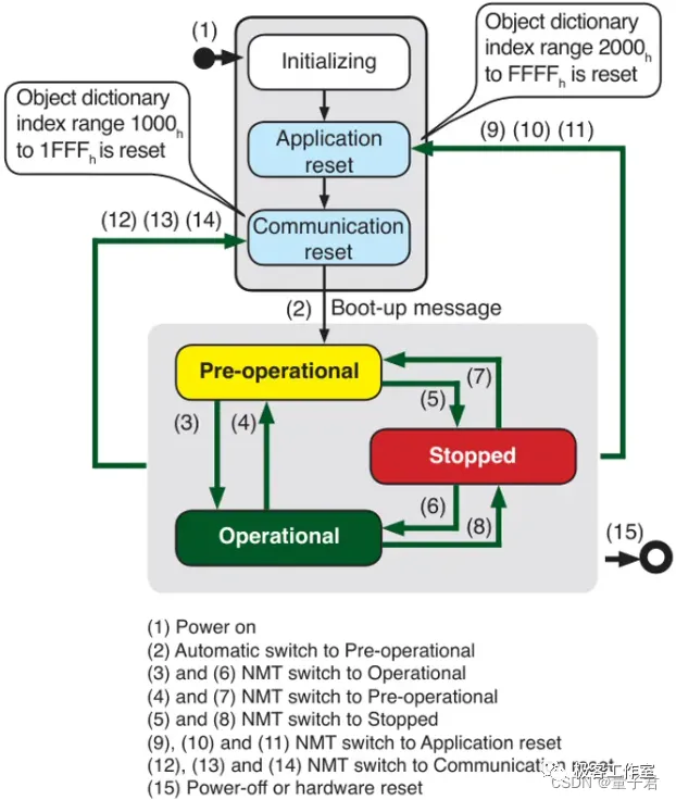
NMT node status switch:
-
Message operations supported in various states:
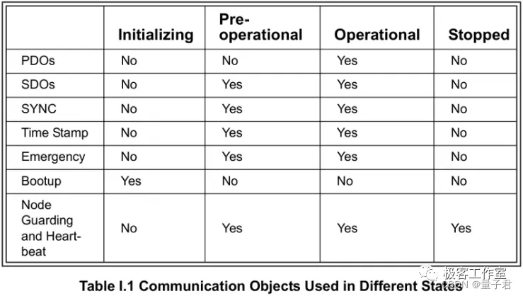
-
Online message:
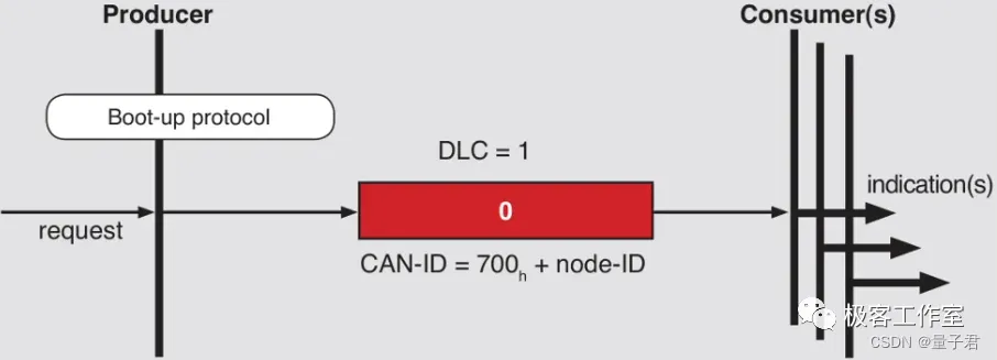
-
Heartbeat message:
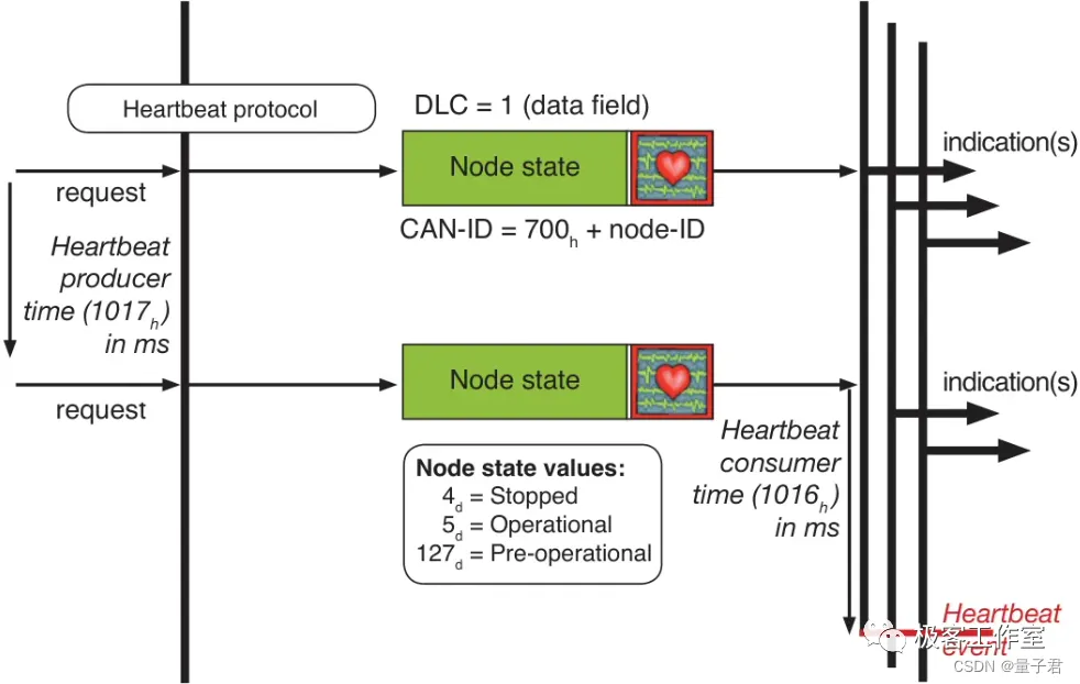
-
NMT message:

8. Timestamp Protocol
The NMT host sends its own clock to provide a common time reference for each node in the network.

9. Synchronization Protocol
This message object mainly realizes the synchronous transmission of the entire network. Generally, the synchronous message is sent by the NMT host.

10. Emergency Message Protocol

Summarize
CANopen is a high-level communication protocol based on the CAN (Controller Area Network) bus, which is widely used in automation and embedded systems. This chapter aims to provide detailed CANopen related knowledge, best practices and practical application cases. Including but not limited to CANopen standards: In-depth explanation of CANopen specifications, including but not limited to the management of communication objects (COB-ID), process data objects (PDO), service data objects (SDO) and network management (NMT) and other core concepts.
end
A bite of Linux
Follow and reply【 1024 】 to get a large amount of Linux information
Collection of wonderful articles
Recommended articles


 京公网安备 11010802033920号