Make a flameless electronic candle using simple electronics and LEDs
Source: InternetPublisher:司马缸砸光 Keywords: led electronic equipment electronic candle Updated: 2024/12/27
Candles have been very useful since ancient times, guiding mankind at night even before Edison came up with the idea of the light bulb. Today, from churches to kitchens, candles not only provide lighting when needed, but also add beauty and provide a sense of warmth. While regular candles work fine, they quickly melt, making the place dirty and sometimes also a fire hazard if left unattended. So, in this tutorial, we will use some simple electronics and LEDs to make a flameless electronic candle. Moreover, this smart candle will automatically turn on at night or in the dark and turn off during the day.
Required Materials
LM358 Integrated Circuit
LDR (Light Dependent Resistor)
1M and 1K resistors
Light Emitting Diode
10K Pot
12V female DC power jack and 12V adapter
Cardstock and perforated board
LM358 – Operational Amplifier Comparator
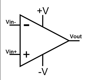
The brains behind this circuit is the LM358 IC, which acts as a comparator in this particular design. Before we dive in, let’s take a brief look at what it is. The LM358 is an Operational Amplifier (Op Amp) IC. This IC consists of two operational amplifiers that can handle voltages between 3.3V to 32V and has a very low supply current consumption of 500μA. The IC looks like this:

It is commonly used to build simple comparator and amplifier circuits and can also be found in active filter circuits, waveform shapers, etc. In this project, we will use LM358 as a voltage comparator. Voltage comparator is used to compare two voltages and find out which one is greater than the other and then turns the output high or low based on that voltage. So, if we apply voltage to the inverting and non-inverting inputs and if the voltage on the non-inverting input is greater than the voltage on the inverting input, then the output becomes high and vice versa, the output becomes low. This project works exactly on this principle. The voltage comparison formula is as follows:
V OUT =AO (V in+ - V in- )
Where AO is the open loop gain of the operational amplifier. Vin+ is the input voltage at the non-inverting input and Vin- is the input voltage at the inverting input. Therefore, if Vin+ is greater than Vin- then the output will be high, otherwise it will be low.
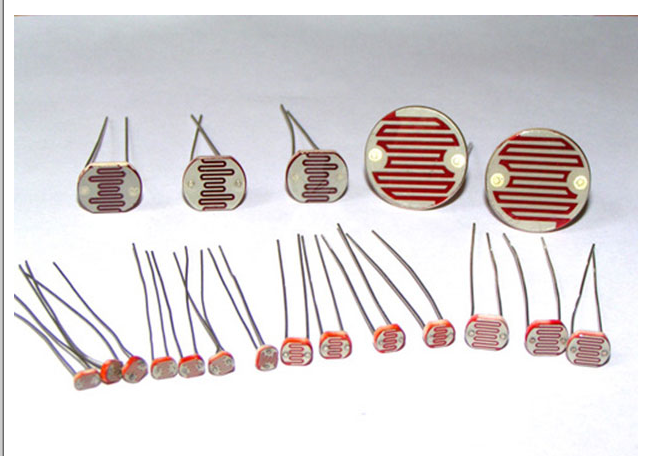
LDR
If the op-amp is the brain of our circuit, then the LDR is the sensory organ. A light-dependent resistor (LDR) or photoresistor is a light-controlled resistor. Its resistance decreases as the light intensity increases and vice versa. In fact, when light is incident on the LDR, the semiconductor absorbs the photons of light, the bonding electrons jump to the conduction band, and the resistance decreases due to photoconductivity.
Circuit diagram and description
The circuit is not difficult. Given below is the complete circuit diagram of the electronic candle.
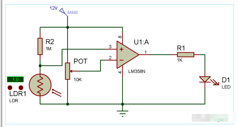
As shown in the circuit diagram, connect a 1K resistor to pin 1 of the IC and then connect the positive leg of the LED to this resistor and the negative leg to ground. Now connect the middle pin of the 10K potentiometer to pin 2 of the IC and connect ground and 12V to the remaining pins of the potentiometer. Connect a 1M resistor to 12V and connect the LDR in series with this resistor. Now, connect the other end of the LDR to the ground of the circuit. Connect the common point of the LDR and the 1M resistor to pin 3 of the IC. Connect 12V to pin 8 and ground to pin 4 of the IC and you are ready. You don't need to be very picky about the resistors, we have already connected them. But make sure the resistor connected to the LDR is megohms and the resistor with the LED is a few thousand.
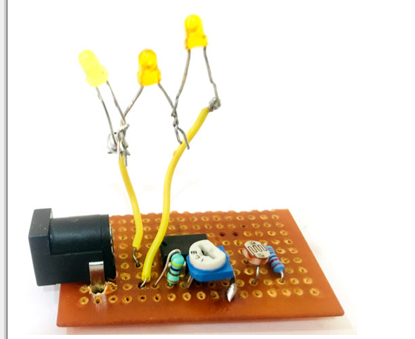
We built the complete circuit on a dummy board to make it compact and easy to use. It really is a simple circuit, you just need to sharpen your soldering skills and start designing it. First, mount the 12V female DC power jack on the perfboard. Keep the pin configuration of this jack in mind while designing the circuit. As shown in the image below:
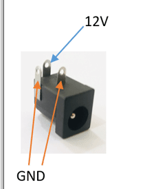
As we have discussed above about the pinout of op-amp, resistors and LDR have no polarity. After the soldering work is completed, the board should look like the following image.
Smart Electric Candle - Working
After designing the circuit on the perfboard and soldering it, connect the 12V adapter to the female jack and your LED must glow. Now, to calibrate the comparator, adjust the 10K potentiometer to a level where the LED just turns off. Now cover the LDR with your hand and you will see the LED light up. You can adjust the sensitivity of the LDR by adjusting the potentiometer.
Now, let's understand how this candle works. As we already know, in darkness, the resistance of the LDR increases to megohms and decreases to a few hundred ohms as the light intensity increases. So since the resistance is very low, the voltage across the non-inverting signal is very low compared to the inverting end, because we have connected the 10K pot. So in this case, the output voltage is also low, so the LED does not turn on. But in darkness, the resistance increases to megohms, which is very high compared to the 10K pot, so the LED glows.
Adjusting the pot will manipulate the sensitivity. By sensitivity, I mean at what intensity of light your comparator turns on the LED. If you adjust the pot close to the LED, then it will detect tiny darkness as well. But if you adjust it far away before the LED lights up, then it will only detect high darkness. You can also test the sensitivity by placing your hand in front of the LDR. If it detects your hand far away, it is highly sensitive, if you need to cover it to light up the LED, it is not that sensitive.
If you want to use multiple LEDs then it's not a problem. Connect two or three LEDs in series and finally connect them to where we connected a single LED and its perfect. But make sure your comparator can provide enough current to power all the LEDs.
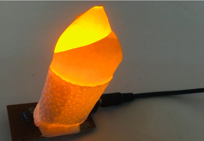
To make the candle, you can use anything to cover the LED. I used card stock and tissue paper. Roll up the card according to the size of the LED and cut a flame shape or any shape you want from it to make it look attractive. Cover the LED with this candle and you have made your own smart electronic candle.
- Diode-based clipping circuit
- Beautiful crown wreath made with LED
- Analysis of three simple electronic dice circuits
- How does RCCB work?
- LED lights that “drain” battery power
- A practical automatic electronic welcome circuit
- AD108 frequency multiplier capable of inputting asymmetric square wave
- Symmetrical output three-way frequency circuit (74LS109, 74LS113)
- Pulse frequency doubling circuit composed of CD4013
- Pulse frequency multiplier composed of gate circuit (CD4011)
- MAX1577V/MAX1577Z driving white LED circuit diagram
- BA6104 five-digit LED level meter driver integrated circuit
- heartbeat sensor
- Dark activated LED flash circuit
- Simple light-emitting display logic pen circuit
- Level display circuit diagram composed of LED level meter driver integrated circuit
- Wall wire detection circuit
- Constant temperature measurement circuit
- Quiz quizzes circuit
- LED billboard decorative light circuit


 京公网安备 11010802033920号