Analysis of three simple electronic dice circuits
Source: InternetPublisher:aerobotics Keywords: Circuit Analysis Updated: 2025/01/03
In this post, we discussed 3 different ways to create electronic or digital versions of dice that can be used to get random numbers between 1 and 6 using an LED display or a digital display.
1) Electronic dice using IC 4017
In this first design, we will learn how to make electronic dice using IC 4017.
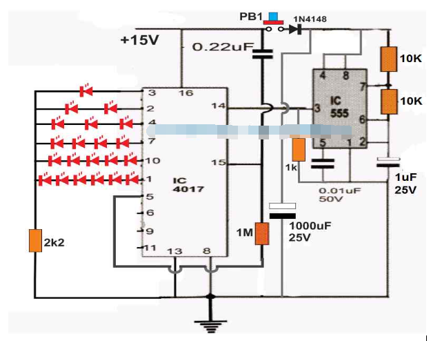
The circuit diagram of Electronic Dice using IC 4017 is shown in the image below.

The working of this 4017 IC based dice circuit is very simple. As we know, when the clock signal is fed to pin #14 of 4017 IC, the output of IC starts sequencing from pin #3 onwards to pin #11.
But since here pin #5 is connected with reset pin #15 of IC, the output can only sequence to pin #1 and return to pin #3 for the new sequence.
This sequence will repeat itself as long as the clock frequency is applied at pin #14 of the IC.
This clock frequency is imposed by IC 555 which is configured as a free running stable multivibrator with a high frequency output.
When push button PB1 is pressed for a moment and released, the capacitor 1000uF gets fully charged and supplies power to IC 555, which uses this power and remains on for a few seconds, allowing IC 4017 to quickly sequence on the output pin.
When the charge inside the 1000uF capacitor is completely drained, IC 555 switches off and stops providing clock pulses to IC 4017. The output sequencing of IC 4017 now stops to a randomly selected IC output between pin #3 and pin #1.
It can be seen that the output of the IC is connected with a series LED, and when the sequencing stops, the LED lights up and indicates the random dice number.
2) Simplified 4017 dice

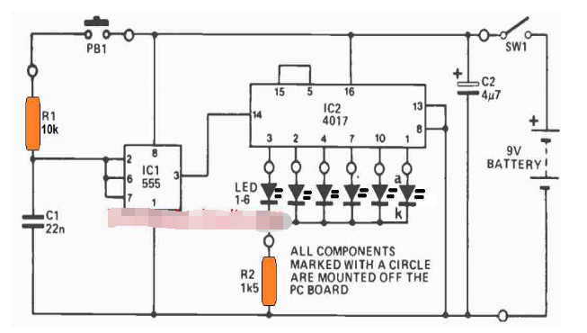
The IC 4017 Electronic LED Dice circuit shown above works the same as the first diagram except the number of LEDs used limits the IC to one LED per output. When the button is pressed, the IC 555 begins to oscillate at a very high speed causing the IC 4017 output to sequence from pin #3 to pin #1 at an equivalent high speed. The high speed sequencing makes it difficult for the user to realize exactly where the sequence will stop after the button is released.
So when the button is released, the sequencing stops abruptly at some random output pin of the IC which indicates the corresponding dice number as indicated by the LED. For example, if the LEDs are labeled from 1 to 6, corresponding to output pin #3 to pin #1, then if the sequence is assumed to stop at pin #7, lighting up the LED at pin #7 will indicate the dice number is 4, and so on.
3) Dice circuit using CMOS IC
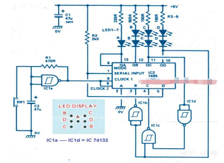
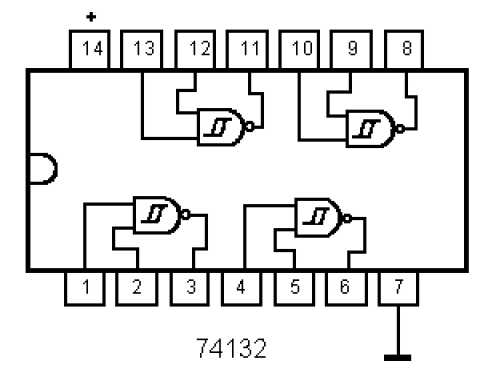
The next electronic dice circuit uses only a few ICs (74132 and 7495) to produce a real dice display.
When the push button switch SW1 is pressed, the dice circuit starts counting rapidly, and once the button is released, the IC stops counting and lights up the LEDs, making them represent any number between 1 and 6 randomly.
Circuit Description
The 7495 is actually a 4-bit parallel access shift register. The chip can work either like a shift register or as a parallel load at the input AD.
Mode control has no input to control the above two functions of IC 7495.


When the mode is in the high state, data is transferred to Qa-Qd through input AD by the subsequent negative-going clock edge.
When MODE is in the LOW state, data is transferred through Qa - Qd by subsequent negative-going clock edges.
By connecting the mode control to Qa, it is ensured that the register alternates between load and shift, making the input word a function of the existing output word.
Using some basic logic, registers were eventually designed to implement counting numbers, randomly toggling LEDs in the dice display to mimic the random numbers of a real cube type dice.
Remember, as long as the output is logic low, the LED will be on.
IC1a is configured like a standard Schmitt oscillator and provides clock pulses to the registers.
Switch SW 1 is used to stop the oscillator and inhibit the counting process. So to get the dice number the user has to press SW1 which will freeze the counting and give the user a random dice number.
When power is first applied, the register may start with an invalid count, but after a few clock cycles it will create a legal count, after which it will continue to operate in that particular sequence.
- Classification and characteristics of operational amplifiers, classification and characteristics of operational amplifiers
- Basic characteristics/working principles and application circuits of tunnel diodes
- How to Build a Simple Temperature Indicator Circuit Using NTC and PTC Thermistors
- Share a Motorola amplifier circuit
- Structural diagram and function of sliding resistor
- What is the difference between high-side and low-side resistive current sensing
- An example of proportional integral circuit diagram
- Frequency divider that converts 50Hz or 60Hz frequency into 1/60 frequency (CD4040)
- Demonstration device for capacitor charging and discharging process
- Oil level indication circuit made by light emitting diode
- Base bootstrap circuit analysis (b)
- Base bootstrap circuit analysis (a)
- Emitter output circuit analysis (b)
- Emitter output circuit analysis (a)
- Circuit analysis of LED power controller with PFC flyback
- 555 square wave oscillation circuit
- 555 photo exposure timer circuit diagram
- Introducing the CD4013 washing machine timer circuit diagram
- Simple level conversion circuit diagram
- 555 electronic guide speaker circuit diagram for blind people


 京公网安备 11010802033920号