A simple device activator circuit
Source: InternetPublisher:酷到被通缉 Keywords: Activator Updated: 2025/01/10
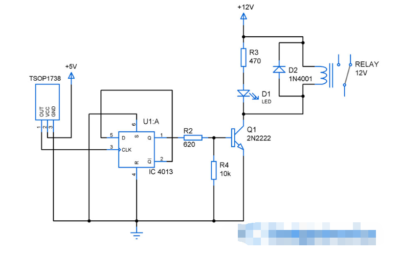
An appliance activator is a circuit that is capable of switching high-power appliances using simple components. Typically, appliance activator circuits use simple buttons and switches as activating elements to trigger the operation of the appliance. However, in this appliance activator, a simple household remote will act as the activating element. This allows this activator to operate without the need for a wired medium.

How the device activator circuit works:
This circuit uses an infrared sensor TSOP1738 which is capable of sensing infrared signals at a frequency of 38Khz, at which most of the household gadget remote controls operate. Hence, any household remote control can be used to activate the above circuit.
It is an active low device that provides a logic 0 as output when an IR signal is incident on it and a logic 1 as output when no signal is present.

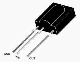
TSOP1738 Pin Diagram
Edge-triggered RS flip-flop IC CD4013
It is used to activate the device. It is wired in such a way that when the input clock level changes, it changes its output state. The output of the IR sensor is fed into the clock pin of this IC. So whenever the IR signal from any remote falls on
When the TSOP1738 is on, the flip-flop changes its output state, causing the device to turn on/off accordingly.
Transistor Q1 2N2222 acts as a switch because the flip-flop cannot provide high current to drive the relay. R2 is used to limit the base current and R4 is used as a pull-down resistor to ensure the transistor state. LED
D1 acts as a function indicator and R3 acts as a limiter for the LED current. The relay is used to switch on/off the device connected to it, you can use any device provided the relay and transistor can handle the rated current of the device. D2 acts as a protection diode to prevent the current from flowing in the reverse direction.
Notice:
You can use this circuit to activate any device, but make sure the transistor and relay can handle the device current without getting damaged.
- Detailed explanation of the working principle of the clapper activated optical circuit
- Share an oil sump/fill pump controller circuit
- Share a board game electronic dice circuit
- Making a Smart Blind Pole Using Arduino Uno and Ultrasonic Sensor
- A novel resonance demonstration device
- Ultrasonic dog chaser made by NE555
- Production of electric water bottle energy saver
- How to use the MP3 player from CATALEX
- How to build an internet-connected traffic meter
- Homemade Micro AC Welding Machine
- How does an optocoupler work? Introduction to the working principle and function of optocoupler
- 8050 transistor pin diagram and functions
- What is the circuit diagram of a TV power supply and how to repair it?
- Analyze common refrigerator control circuit diagrams and easily understand the working principle of refrigerators
- Hemisphere induction cooker circuit diagram, what you want is here
- Circuit design of mobile phone anti-theft alarm system using C8051F330 - alarm circuit diagram | alarm circuit diagram
- Humidity controller circuit design using NAND gate CD4011-humidity sensitive circuit
- Electronic sound-imitating mouse repellent circuit design - consumer electronics circuit diagram
- Three-digit display capacitance test meter circuit module design - photoelectric display circuit
- Advertising lantern production circuit design - signal processing electronic circuit diagram


 京公网安备 11010802033920号