Share a board game electronic dice circuit
Source: InternetPublisher:司马缸砸光 Keywords: Electric dice Updated: 2025/01/03
Electronic dice can be a good and fun alternative to traditional dice when enjoying our board games. We have designed an electronic dice circuit that will generate random numbers from 0 to 6. The feature of this circuit is that the results are highly unpredictable due to a special modulated clock that drives the number generation.
Working principle of electronic dice circuit:
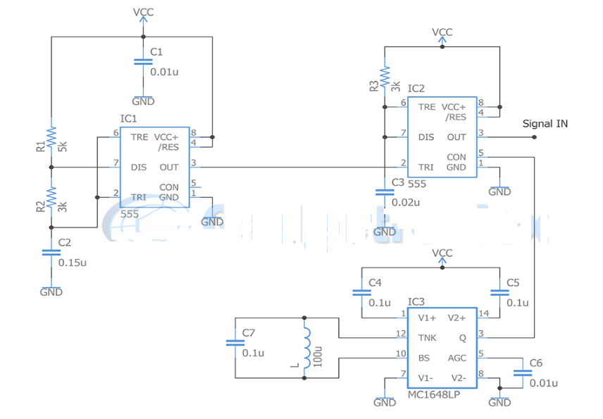
This circuit uses a 4-bit counter to generate a random number between 1 and 6, for this we have created a modulated PWM using 2 timers 555 and a VCO. This will allow us to tell the counter to count numbers from 0 to 7 in a semi-random manner and block the numbers 0 and 7 from appearing.
1) Clock signal generator:

The first part of the circuit generates the signal input to the counter. We need the counter to count from 1 to 6, but not constantly, we should try to do it in a semi-random way, we can make it so that the counter advances the numbers faster for some of the time, and slows down the rest of the "cycles". This can be achieved by using the PWM signal that the counter needs, but in a modulated way.
For this we need a PWM signal and a sinusoidal signal. For this we use a 555 timer in monostable mode and a VCO based on the chip MC1648LP as a sinusoidal signal generator. We input these 2 signals to another 555 acting as a modulator. The result is a PWM signal modulated by the sinusoidal signal and it will have two time periods "PWM and Sine. This results in one period of time when the pulse is shorter and one period of time when the pulse is longer.
2) Counter:

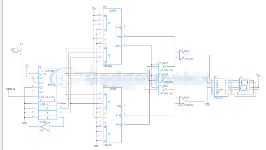
The modulating signal is fed as input to the counter portion of this circuit. If we feed this signal into a 4-bit counter, this will count from 0 to 15 in a semi-random fashion. The count will increase with each pulse, but the timing of this increment will vary depending on the modulating PWM signal input.
We need to limit the counter to count from 0 to 7, so bit 4 will be used as a reset signal. Switch button S1 will tell the counter to count when pressed. What we have done so far is allow the counter to count from 0 to 7 in a semi-random manner, but we need it to count from 1 to 6. To do this we pass the signal to two comparator chips 7485N, which will tell us whether the number we generated is 0 or 7.
When this condition is true, we force the display to show either 1 or 6. This operation is performed using gates OR and AND. After making this restriction, we send the resulting signal to the 74LS47N chip which converts the BCD signal to a signal which the 7-seg display interprets to show the corresponding number.
Parts Required:
Battery – 12V
C1, C2, C3, C4, C5, C6, C7 – 0.01u, 0.15u, 0.02u, 0.1u, 0.1u, 0.01u, 0.1u
D1
IC1, IC2 – 555 (2)
IC3 – MC1648LP
IC4 – 74LVC1G04DCK
IC5-74AC11D
IC6 – 74AC32D
IC7 – 74LS47N
L – 100uH
R1- 5k, R2 & R3 – 3k
Push button switch – S1
V1 74160N
V2 7485AN
V3 7485AN
- Making a Smart Blind Pole Using Arduino Uno and Ultrasonic Sensor
- How to make a clock Bluetooth IOT speaker using Arduino
- A simple memory reader/writer
- Electronic Rat Killer Circuit
- Easy-to-make integrated circuit signal tracker circuit
- Using VPX-based PCIe systems for asynchronous clocking
- How to use RFID to create an automatic roll call attendance system
- How to create image processing solutions using HLS capabilities
- Driving Large TFT-LCD Displays with Space-Saving Triple-Output Regulator
- DIY a temperature and humidity monitoring system
- How does an optocoupler work? Introduction to the working principle and function of optocoupler
- 8050 transistor pin diagram and functions
- What is the circuit diagram of a TV power supply and how to repair it?
- Analyze common refrigerator control circuit diagrams and easily understand the working principle of refrigerators
- Hemisphere induction cooker circuit diagram, what you want is here
- Circuit design of mobile phone anti-theft alarm system using C8051F330 - alarm circuit diagram | alarm circuit diagram
- Humidity controller circuit design using NAND gate CD4011-humidity sensitive circuit
- Electronic sound-imitating mouse repellent circuit design - consumer electronics circuit diagram
- Three-digit display capacitance test meter circuit module design - photoelectric display circuit
- Advertising lantern production circuit design - signal processing electronic circuit diagram


 京公网安备 11010802033920号