Make a Simple Darkness Detector Circuit
Source: InternetPublisher:酷到被通缉 Keywords: led detector LDR Updated: 2024/12/27
The absence of light is the cause of darkness, we can use a light dependent resistor (LDR) to automatically detect darkness or light intensity. This circuit can be integrated with other electronic circuits or projects to control the light of a small bulb to automatically light up the street lights throughout the city. In this project, we will make a simple darkness detector circuit.
Components Needed to Build a Dark Detector
The darkness detection circuit is a very simple circuit that requires only a few components. The complete component list is as follows:
LDR
Leading
1K Ohm - Resistor
50k Ohm - Resistor
BC547 – BJT
9V battery
Breadboard
Working Principles
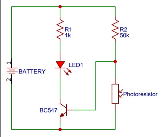
This circuit is based on LDR also known as light dependent resistor. The resistance of LDR depends on the intensity of light. The 50k resistor and LDR form a voltage divider circuit. When the intensity of light falling on LDR is high, it will have a high resistance and hence the voltage divider will give a low output to the base pin of BC547 BJT. BC547 is an NPN transistor and when the BJT is in the on state, i.e. the emitter-base junction is in forward biased state. The electron path of our LED is completed and hence the LED will light up.
Circuit Schematic
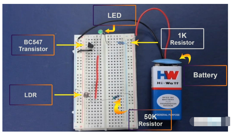
To make the circuit, we connected the battery in parallel to the LED with a 1K Ohm resistor, the positive terminal or the longer leg of the LED is connected to the end of the resistor and the negative terminal or the shorter leg of the LED is connected to the collector of our BJT. The emitter of the BJT is connected to the negative terminal of the battery and the base of the BJT is connected to the junction connecting the LDR and the 50K Ohm resistor. The other end of the 50k resistor is connected to the positive rail of the battery and the other end of the LDR is connected to the negative rail of the battery. To simplify the connections, we connected everything on a breadboard. The circuit diagram of the darkness detector is given below:


After connecting the components to the breadboard, we tested it by blocking the light falling on the LDR and the circuit worked fine. To see it in action you can check out the video at the bottom of the page.
in conclusion
Darkness detector circuit using LDR is a very simple circuit which can have many real world applications.
- How to test whether the multimeter is working properly
- Bat sound detection circuit
- Fire detector made with photodiode
- Design of blood analyzer
- A simple electronic muscle stimulator circuit
- PHGS-4 computer multi-channel industrial acidity meter circuit 01
- AC ammeter circuit
- DC power meter
- High current, high power amplifier circuit
- A simple no-load self-stop circuit for welding machines
- MAX8630Y/ MAX8630Z driving white LED circuit diagram
- Driving circuit diagram of a low-power LED bulb
- Three-phase phase loss alarm light circuit
- "clairvoyance" charger circuit diagram
- CdS photoresistor as electronic photometric element circuit diagram
- Positive terminal buck/boost LED constant current drive circuit diagram
- Positive terminal buck/boost LED constant current drive circuit diagram
- Biogas concentration detection line
- Electric blanket internal disconnection measurement circuit
- Digital camera flash control circuit


 京公网安备 11010802033920号