Making a Smart Blind Pole Using Arduino Uno and Ultrasonic Sensor
Source: InternetPublisher:supremeOne Keywords: Ultrasonic sensor Arduino obstacle detection Updated: 2024/12/19
Obstacle detection is one of the biggest concerns for blind people. Shown here is a smart blind pole using Arduino Uno and Ultrasonic sensor . The main goal of this project is to help blind people to walk easily and alert them when their walking path is blocked by other objects or people. As a warning signal, a voice module is connected in the circuit which gives a voice warning according to the direction of the object, for example, if the object is on the left side, then it will say “Beware object on the left side”.
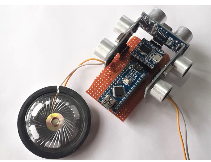
This smart joystick will be connected with three ultrasonic sensors on the left, right, and center to sense the distance from any obstacles, a JQ6500 voice sound module for warning signals, and a 9V battery to power the setup.
Components required for smart blind poles
Arduino Nano
3 × Ultrasonic Sensors
JQ6500 Voice Module
8Ω speaker
1 KΩ resistor
JQ6500 Voice Module
The JQ6500 voice module is ideal for playing messages on loudspeakers, such as fire alarms, train and bus alarm systems, business hall prompts, equipment failure alarms, etc. It can decode MP3, hard-coded MP3 or WMV format files into audible voice formats. It is equipped with a 24-bit D/A converter with a dynamic range of 90dB and supports 8 / 11.025 / 12/16 / 22.05 / 24/32 / 44.1 / 48 kHz sampling rates. The MP3 files can be controlled by buttons or through serial communication protocols.

To upload an MP3 file to the onboard memory:
MP3 files can be uploaded to the JQ6500's onboard memory using a Windows computer (Mac or Linux users will need to use the JQ6500-28p and an SD card). The same steps are given below:
Connect the board to your computer via the Mini USB connector.
A new "CD- ROM" drive will appear on your computer, double click it and open the application called "MusicDownload.exe".

Some JQ6500-16P devices do not have MusicDownload.exe installed. If you cannot find the MusicDownload.exe program, you can download the zip file that contains it.
The application is in Chinese, so to upload the file, open the .exe file and click on the second tab from the left.
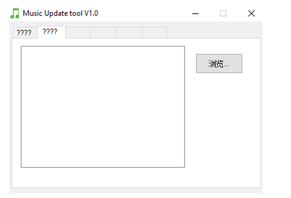
Then click on the file chooser tab in the upper right corner.
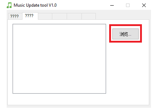
The file chooser will open, select all the mp3 files you want to upload click the open button on the file chooser
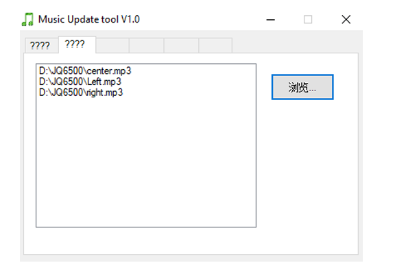
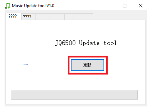
Click back to the first tab and click the button to upload the file
Intelligent blind pole circuit diagram
The complete circuit diagram of the smart blind pole is shown below. It is very simple, we only need to connect three ultrasonic sensors and a JQ6500 voice module.
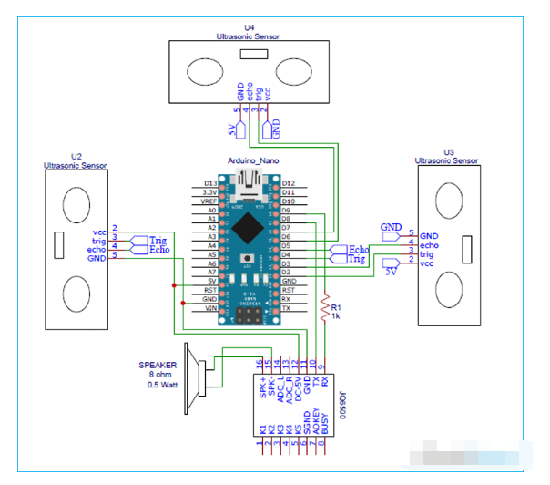
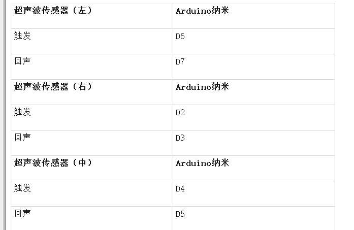
The entire board is powered by a 9V battery. The brain of the circuit is the Arduino Nano. Three ultrasonic sensors are used to detect obstacles to the left, right and front of the joystick. Two of the four pins of these three sensors, namely VCC and GND, are connected to 5V and GND of Arduino. The remaining two pins – TRIG and ECHO are connected to Arduino as shown below.
The JQ5600 MP3 module is a 3.3V logic module, so it cannot be connected directly to the Arduino's IO pins, but it can be powered by the Arduino's 5V power line. The MP3 module's RX and TX pins are connected to the Arduino Nano's digital pins 9 and 8. A 1kΩ resistor is placed between the Arduino digital pin 9 and the MP3 module RX to drop the Arduino's 5V voltage.
Arduino Program for Smart Blind Pole
Once we have the hardware ready , we can connect the Arduino to our computer and start programming. The complete code for this project is given at the bottom of this page; you can upload it directly to your Arduino board. However, if you want to know how the code works, read further.
This code uses JQ6500_Serial.h and SoftwareSerial.h libraries. The SoftwareSerial library comes pre-installed with the Arduino IDE whereas the JQ6500 Serial library can be installed from the given link.
As usual, start the code by including all the required libraries and defining all the pins used in this project.
#include
#include
#include
JQ6500_Serial mp3(8,9);
int left_trig
Then in the setup() function, we initialize the input and output pins. In our program, the trigger pins of all three sensors are output devices, and the echo pin is an input device. We also initialize the serial monitor and the JQ6500 voice module.
  pinMode(left_trigPin, OUTPUT);
  pinMode(left_echoPin,INPUT);
  pinMode(right_trigPin, OUTPUT);
  pinMode(right_echoPin, INPUT);
  pinMode(center_trigPin, OUTPUT);
  pinMode(center_echoPin, INPUT);
  SerialNumber.Start(115200);
  mp3.start(9600);
  mp3.reset();
In the main loop, we are reading the data of all three sensors, i.e., left, right, and center. We first read the sensor data of the ultrasonic sensor to know the distance and then calculate the distance using the time between the trigger and the ECHO received. The distance calculation formula is as follows:
digitalWrite(left_trigPin, HIGH);
delayMicroseconds(10);
 digitalWrite(left_trigPin, LOW);
 duration = pulseInput(left_echoPin,HIGH);
 distance = (duration/2) / 29.1;
If the measured distance is more than 50cm, no warning will be given. However, if it is less than 50cm, the voice module will be triggered to play a voice warning.
if (distance < 50) {
    Serial.print("left distance");
    Serial.print(distance);
     mp3.playFileByIndexNumber(2);
    }
The same logic is used for all three sensors. This program can be easily adapted to your application by changing the values we use to compare. If a false alarm is triggered, you can use the serial monitor to debug.
Testing the Smart Arduino Blind Rod
Finally, it is time to test our blind cane Arduino project. Make sure that the connections are done as per the circuit diagram and the program is uploaded successfully. Now, power the setup with a 9V battery and you should start seeing results. Move the blind cane closer to the object and you will notice a voice warning based on the direction of the object. For example, if the object is on the left side, then it will say “Beware of left object”.

#include
#include
#include
JQ6500_Serial mp3(8,9);
int left_trigPin = 7;
int left_echoPin
= 6; int right_trigPin = 2;
int right_echoPin = 3;
int center_trigPin = 4;
int center_echoPin = 5;
void setup() {
pinMode(left_trigPin, OUTPUT);
pinMode(left_echoPin, INPUT
); pinMode(right_trigPin, OUTPUT);
pinMode(right_echoPin, INPUT
); pinMode(center_trigPin
, OUTPUT); pinMode(center_echoPin, INPUT);
Serial.start(115200) ; mp3.start
(9600);
mp3.reset();
mp3.setVolume(50);
mp3.setLoopMode(MP3_LOOP_NONE);
}
void loop(){
left();
right();
center();
}
void left(){
delay(500);//read will be done after....
milisecondsSerial.println(" ");
int duration, distance;
digitalWrite(left_trigPin,HIGH);
delaymicroseconds(10);
digitalWrite(left_trigPin,LOW);
duration = pulseIn(left_echoPin,HIGH);
distance = (duration / 2) / 29.1;
//distance = duration * 0.034 / 2;
if (distance < 30) { // Change the number for long or short distance.
Serial.print("left distance");
Serial.print(distance);
mp3.playFileByIndexNumber(2);
}
}
void right(){
delay(500);// the read will be made after....miliseconds
Serial.println(" ");
int duration, distance;
digitalWrite(right_trigPin, HIGH);
delaymicroseconds(10);
digitalWrite(right_trigPin, LOW);
duration = pulseIn(right_echoPin, HIGH);
distance = (duration / 2) / 29.1;
if (distance < 30) { // Change the number for long or short distance.
Serial.print("Correct distance");
Serial.print(distance);
mp3.playFileByIndexNumber(3);
}
}
void center(){
delay(500); // Read will be made after .... milliseconds
Serial.println(" ");
int duration, distance;
digitalWrite(center_trigPin, HIGH);
delayMicroseconds(10);
digitalWrite(center_trigPin, LOW);
duration = pulseIn(center_echoPin, HIGH);
distance = (duration / 2) / 29.1;
if (distance < 30) { // Change the number for long or short distance.
Serial.print("Center distance");
Serial.print(distance);
mp3.playFileByIndexNumber(1);
}
}
- How to Make a Digital Taxi Meter Using Arduino
- Build a Raspberry Pi-based QR code scanner
- Design of a drone wildlife counting system using FOMO object detection algorithm
- Design a pet NFC timer feeder
- DIY an indoor and outdoor webcam
- How to build an autonomous robot using the DonkeyCar platform
- Satellite TV Set Top Box Remote Controller
- How to Build a Low-Cost Arduino MiniCNC Plotter
- Driving Large TFT-LCD Displays with Space-Saving Triple-Output Regulator
- Laser constant power control circuit
- Ultrasonic sensor thyristor drive circuit
- Transistor drive circuit for ultrasonic sensor
- Ultrasonic sensor receiving amplifier circuit
- How does an optocoupler work? Introduction to the working principle and function of optocoupler
- 8050 transistor pin diagram and functions
- What is the circuit diagram of a TV power supply and how to repair it?
- Analyze common refrigerator control circuit diagrams and easily understand the working principle of refrigerators
- Hemisphere induction cooker circuit diagram, what you want is here
- Circuit design of mobile phone anti-theft alarm system using C8051F330 - alarm circuit diagram | alarm circuit diagram
- Humidity controller circuit design using NAND gate CD4011-humidity sensitive circuit


 京公网安备 11010802033920号