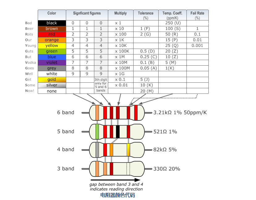
How to read resistor color codes? Resistor color codes illustrated
Source: InternetPublisher:拳制龙 Keywords: resistor Updated: 2025/01/21
How to read resistor color codes?
Resistor color coding uses colored bands to quickly identify the resistance value of a resistor and its tolerance percentage. The physical size of the resistor indicates its power rating. Brown, red, green, blue, and purple are used as tolerance codes for 5-ring resistors only.
Hold the resistor with these grouping bands on the left. Always read the resistor from left to right. - Resistors never start with a metal band on the left. If your resistor has a gold or silver band on one end, the resistor has a 5% or 10% tolerance.
Resistor Color Codes Illustrated
Resistor values are usually indicated by color codes. Color ring resistors indicate the parameters of the resistor based on the different colors of the surface. 4-color and 5-color resistors are commonly used. 4-color ring resistors are usually carbon film resistors. It uses the first 3 color rings to indicate resistance. The fourth point is used to indicate errors. 5-color ring resistors are usually metal film resistors, and the 5-color ring is higher in precision than the 4-color ring. The 4th color indicates the resistance value, and the fifth indicates. The color code is given by several bands. Together, they specify the resistance value, tolerance, and sometimes reliability or failure rate. The number of bands varies from three to six. At least, two bands indicate the resistance value, and one band is used as a multiplier. The resistance values are standardized, and these values are called preferred values.

4 band resistor
The four-band color code is the most common variation. These resistors have two resistance value bands, a multiplier and a tolerance band. In the example on the left, these bands are green, blue, red, and gold. By using the color code table, you can see that green represents 5 and blue represents 6. Therefore, the value is 56 100 = 5600Ω. The gold band indicates that the tolerance of the resistor is 5%. Therefore, the resistor value is between 5320 and 5880Ω. If the tolerance band is left blank, the result is a 3-band resistor. This means that the resistance value remains the same, but the tolerance is 20%.

5 band resistor
High-precision resistors have an extra band to indicate the third significant digit. So the first three bands indicate significant digits, the fourth band indicates the multiplication factor, and the fifth band indicates the tolerance. There are exceptions to this. For example, sometimes the extra band indicates failure rate (military specifications) or temperature coefficient (older or specialized resistors).

6 band resistor
Resistors with 6 bands are often used for high precision resistors with an additional band to specify the temperature coefficient (ppm/K). The most common color of the sixth band is brown (100ppm/K). This means that for a temperature change of 10°C, the resistance value can change by 0.1%. For special applications where the temperature coefficient is critical, other colors are used.
Color code anomalies
Reliability belt
Resistors produced to military specifications sometimes include an additional band to indicate reliability. This is specified as a failure rate (%) per 1000 hours of service. This is rarely used in commercial electronics. Most reliability bands can be found on four band resistors. More information on reliability can be found in the US military manual MIL-HDBK-199.
Single black band or zero ohm resistor
A resistor with a single black band is called a zero ohm resistor. In principle it is a wire connection that has only the function of connecting the traces on the PCB. The advantage of using a resistor assembly is the ability to use the same automated machine to place the component on the circuit board.
5-band resistor with 4th gold or silver band
The exceptions are five band resistors with a fourth gold or silver band, which are used for specialized and older resistors. The first two bands represent the significant digits, the 3rd is the multiplier, the 4th is the tolerance, and the 5th is the temperature coefficient (ppm/K).
Deviation color
For high voltage resistors, gold and silver are often replaced with yellow and gray. This is to prevent the inclusion of metal particles in the coating.
- Principle set of zero-crossing detection circuit advantages and disadvantages
- How does sand become chips?
- How to calculate the value of capacitors in parallel?
- What is power factor and three ways to improve it
- Share a Motorola amplifier circuit
- Circuit diagram of an example of differential and integral circuits
- Frequency divider that converts 50Hz or 60Hz frequency into 1/60 frequency (CD4040)
- Using Monostable Trigger to Construct Pulse Delay Circuit
- Odd-frequency counter with symmetrical output waveform (μL9020)
- Digital frequency multiplier (LM108, LM111)
- How to choose and use resistors?
- Laser detection anti-theft alarm circuit
- OTL power amplifier circuit in transistor radio a
- Direct broadcast radio circuit
- Household gas alarm circuit composed of gas sensor
- Soil moisture detection and display circuit
- Single tube DC coupled amplifier circuit
- Step-adjustable integrated regulated power supply
- Series voltage stabilizing circuit with amplification link
- Switching constant current source using integrated voltage regulator


 京公网安备 11010802033920号