Principle set of zero-crossing detection circuit advantages and disadvantages
Source: InternetPublisher:清宁时光 Keywords: Zero Crossing Detection Updated: 2025/01/21
Principle of zero-crossing detection circuit
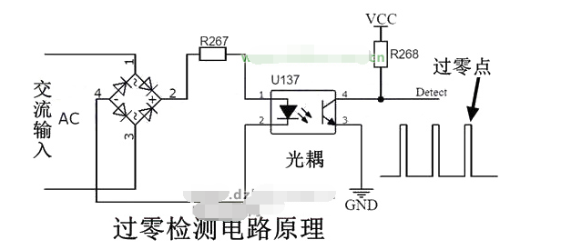
Alternating current has directionality, and can be rectified into pulsating direct current through a rectifier bridge, and then output the zero-point signal after optical coupler isolation. Alternatively, a bidirectional optical coupler solution can be used to output the zero-point signal. Here, a rectifier bridge solution is used to design a zero-crossing detection circuit, and the designed circuit diagram is shown in the figure below.

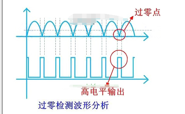
After the AC passes through the rectifier bridge, it becomes pulsating DC. The negative half cycle of the AC is flipped to positive. The optocoupler can be turned on at any point other than the zero point, and the optocoupler is turned off near the zero point. The output end of the optocoupler is connected to a pull-up resistor. The waveform analysis is as follows:
Positive half cycle: the light-emitting diode of the optocoupler is turned on, the output terminal is turned on, and the output signal is low level;
Negative half cycle: the light-emitting diode of the optocoupler is turned on, the output end is turned on, and the output signal is low level;
Near zero point: the light-emitting diode of the optocoupler is cut off, the output end is cut off, and the output signal is high level.
The output waveform is shown in the figure below.

As can be seen from the waveform above, as long as a high level is detected, it can be determined that the zero point has arrived. At this time, as long as the coil of the contactor/relay is controlled, the contact can be ensured to be disconnected when the AC zero current is the smallest, thereby suppressing the generation of arcs. Multiple contacts play a good protective role, extending the life of the contacts and ensuring the safety of property.
Advantages and Disadvantages of Zero Crossing Detection Circuit
The zero-crossing detection circuit is an auxiliary means of suppressing arcs. It informs the processor of the arrival of the zero point in the main control circuit, and the processor promptly disconnects the main circuit at the zero point with the minimum current, thus preventing the generation of arcs to the greatest extent. However, this circuit is only applicable to AC circuits, not DC circuits. There is currently no very effective means to solve the arc in the DC control circuit, and it still relies on magnetic blowing, arc extinguishing chambers, arc extinguishing grids, and filling with inert gas.
Although solid-state relays have electronic contacts and do not have arc problems, electronic contacts have limited current capacity and require the installation of larger heat sinks, which increases cost and size.
In short, arcing is an industry problem and is inevitable. Currently, the means of suppressing arcs are very limited. Engineers in the industry have been working hard to research effective ways to suppress arcs.
- Ideal characteristics of operational amplifiers/pin configurations/gain types/primary applications
- Causes and solutions for noise in digital Class D amplifiers
- What is the difference between CPLD and FPGA?
- Causes of PCB deformation How to prevent circuit board bending and warping
- How does RCCB work?
- What types of force sensors are there?
- Introduction of TDA4863J/4863AJ TV field scanning IC
- Homemade air conditioner outdoor unit shutdown indicator
- Homemade 100-base addition and subtraction counting circuit
- Digital control frequency division circuit composed of MC4018
- Zero-crossing detector circuit diagram E
- Zero-crossing detector circuit diagram D
- Zero-crossing detector circuit diagram C
- Zero-crossing detector circuit diagram B
- Zero-crossing detector circuit diagram A
- MOS logic circuit control zero-crossing detector circuit
- Zero-crossing detection thermostat circuit
- 555 square wave oscillation circuit
- 555 photo exposure timer circuit diagram
- Introducing the CD4013 washing machine timer circuit diagram


 京公网安备 11010802033920号