With the development of process technology and market needs, ultra-large-scale, high-speed, low-power FPGAs are constantly being introduced and widely used in the field of high-speed, high-density digital circuit design. SoPC[1] (System on a Programmable Chip) is a SoC design solution based on FPGA. It embeds the core of FPGA and microprocessor on the same chip to form a programmable SoPC system framework. It has a high degree of integration capability, greatly reduces the product volume and the interference of external signals on the system, and greatly increases the reliability, stability and flexibility of the system. This paper introduces a method for realizing LCD control display graphics based on Nios Ⅱ soft-core processor. In the design, the Nios Ⅱ soft-core processor and its "soft" hardware modules related to the display function are customized using Altera's FPGA SoPC Builder to collaboratively realize the software and hardware design of display control.
1 System Design
In the field of industrial control and consumer electronics, LCD display technology is showing more and more forms. This design adopts the design method of liquid crystal display graphics based on NiosⅡ processor. In SoPC Builder, the LCD controller is designed in the form of a custom interface using the bus method. The LCD controller [2] receives user control at one end and implements LCD complex timing at the other end, and integrates multiple functions. Users only need to interact with the simple interface of the controller to achieve the purpose of controlling the LCD, and then write applications to realize functions such as displaying Chinese characters, pictures, and drawing. The design method in this paper greatly reduces the workload, speeds up the data processing speed and scanning frequency, improves the integration of various functional modules, and improves the performance and reliability of the system.
This design finally realizes the display of known graphics by a TFT-LCD controller based on Altera's DE2 development board.
2 Hardware Design
2.1 Overall structure of the system
The SoPC system communicates with other system components based on the Avalon bus. The peripherals in the entire SoPC system design are connected through the Avalon bus module, and the bus specification provides an interconnection model for data transmission between the peripheral ports and the bus module.
The overall structure of the SoPC system designed in this paper is shown in Figure 1.
 [page]
2.2 SoPC system establishment
The configurability of the FPGA-based SoPC solution [3] is reflected in the fact that when building the hardware platform, users can flexibly select the required memory and peripheral interface devices according to the functions they want to achieve, without having to add all the provided components to the system. In this way, each system can be designed specifically according to different functions, thus avoiding the waste of FPGA resources caused by adding useless components. For example, from the overall structure of the system, it can be seen that the basic components required by this system are CPU, SDRAM controller, JTAG-UART, SRAM, timer, and CPI-FLASH connected by a tri-state bridge. Because the TFT-LCD already has a controller, there is no need to add the controller of this component in the form of a custom component in SoPC Builder.
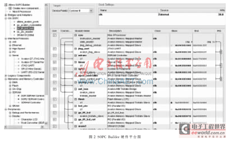
This system is built based on the SoPC Builder tool of QuartusⅡ8.0, which generates system modules using CPU, memory interface and peripheral devices (such as the interface gx_tft_lcd attached to the tri-state bridge added in this design), and automatically generates interconnection logic between the Avalon bus module and the slave device ports on all system components. Since the bus method is used to access the TFT LCD with a controller (TCB8000A), a tri-state interface gx_tft_lcd needs to be manually added to the NiosⅡ system module. Because only one interface is created, HDL files and HAL files are not required, but when setting signals, the required signals should be added according to the Avalon bus tri-state slave port write timing diagram and the control interface of TCB8000A.
After setting up the generation of new components, you can add the newly customized gx_tft_lcd to the Nios system, generate a Nios II system module, and add it to the project. Save and compile, and after passing, you can download the compiled sof file to the FPGA chip. At this point, the hardware work is basically completed.
FIG2 shows the use of the SoPC Builder tool to add generated system modules to the hardware platform for this design.

3 Software Design
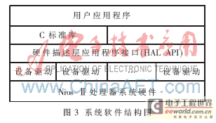
The software programming of the Nios II processor uses the HAL (Hardware Abstraction Layer) system library. The HAI system library [4] provides programmers with a device driver interface for the application to interact with the underlying hardware, which simplifies the development of applications. It also draws a clear dividing line between the application and the underlying hardware driver, thereby greatly improving the reusability of the application, allowing the application to communicate between the system hardware and the application without being affected by changes in the underlying hardware. The HAI API [5] (Application Program Interface) integrates the ANSI C standard library, allowing the upper-level program to access the system hardware and software like accessing the C function library. Software designers do not need to consider the details of the underlying hardware implementation and can directly write applications. The system software structure is shown in Figure 3.

The software system is mainly divided into two parts: system initialization, control of LCD controller and display data processing. [page]
Initialize the system, call the initialization programs of each module of HAL, and define the functions for setting the background color and font color of the LCD display to be used in the subsequent programs.
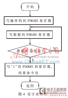
This design uses the bus method [6] to control the timing of the LCD controller (TCB8000A). SoPC Builder is used to add an interface connected to the tri-state bridge and associate the control pin of TCB8000A with the Avalon bus. Since the control timing of TCB8000A matches the timing of the tri-state interface of the Avalon bus, the control purpose can be achieved by simply adjusting the wait and setup time when customizing the interface. A simple write operation is used in the Nios program to generate the Avalon bus timing. It should be noted that TCB8000A only needs one address control line A1, which is connected to the A1 of the bus. Therefore, the write operation should make the address line A1 on the bus meet the timing requirements of TCB8000A for the A1 pin. That is, in parallel mode, the MPU first sends the complete command packet to the write-only register with address F004H (A1=0), and then sends "1" to the register with address F006H (A1=1), ending a command packet and turning on the display. The control board used for address lines A0, A2~A17 has been set, so only A1 needs to be controlled to complete the command input. The flow chart is shown in Figure 4.

The code is as follows:
void SdCmd(alt_u8 Command) //send command
{
IOWR(GX_TFT_LCD_BASE, 0, Command); //A1=0
}
void CmdEnd() //send command
{
IOWR(GX_TFT_LCD_BASE, 2, 1); //A1=1
}
On the basis of controlling the timing, the picture display part of the program [7] first converts the picture to be displayed into data information using the Bmp2HexPro.exe software tool, and adds the picture data information to the project in the form of a header file (picture.h).
The stored images are classified and labeled (e.g., picx1, picx2, picx3, etc.), and then the switch statement [8] is used in the C main program to call the index number representing the image information respectively. The sample program is as follows:
void ShowBMP160(alt_u32 X,alt_u32 Y, alt_u8 picIndex)
{
alt_u8 i,j,k,Buffer[5],*pic;
alt_u16 p;
alt_u32 addr;
switch(picIndex){
case 1: pic=picx1;break;
case 2: pic=picx2; break;
case 3: pic=picx3; break;
default: break;
}[page]
The next step is to assign addresses to the LCD RAM and write the data information of the picture to be displayed into the destination address from left to right in the form of data pointers. The SdCmd() function is a sub-function written by itself to send data commands.
addr=Y*5;
addr=addr<<7;
addr=addr+X*2; //same as addr=X*2+Y*320*2
p=0; //Data ROM pointer
for(j=0;j<10;j++) //sprit one line data to 8 packet
{
SdCmd(0x84);
//send data packet, send a pixel's data to memory
SdCmd(40);
//no of byte in one packet, end a command packet
for(k=0;k<20;k++) //no of pixels in one packet
{
SdCmd(pic[p+1]); //low byte
SdCmd(pic[p]); //high byte
p+=2;
}
CmdEnd();
}
addr+=640; //next line
}
}
The display of Chinese characters and characters is also achieved by defining the PrintGB() function. Similar to the above program, the information to be displayed is sent to the destination address in the form of a command packet, and the sub-function is directly called in the subsequent program for display.
As LCD displays are increasingly used in all aspects of production and life, various processor-controlled LCD display solutions have also emerged. This paper proposes a FPGA-based SoPC solution through the design of the entire system and experiments on the hardware platform, and finally verifies its feasibility on the platform. The advantage of this solution lies in the flexibility of system function improvement. The system can be added, deleted and optimized without changing the hardware platform, which reduces the system cost. This is something that traditional ARM solutions cannot achieve. Since the microprocessor and user logic interface are integrated on a Cyclone chip, programmers can flexibly define the I/O interface, which has better flexibility and reliability based on FPGA [9]. For NiosⅡ-based microprocessors, users can flexibly adjust the hardware logic design according to the size of the display to achieve control of the display without changing its original hardware structure. However, 16-bit microcontrollers can only control fixed-size displays. In the long run, NiosⅡ-based microprocessors can easily upgrade versions by changing their hardware logic configuration, saving costs. Developers can accelerate software algorithms by adding custom instructions to the processor[10] instruction set. Custom instructions can complete complex processing tasks within a single cycle, providing a cost-effective solution for system optimization. [page]
References
[1] Pan Song, Huang Jiye, Zeng Yu. Practical Tutorial of SoPC Technology[M]. Beijing: Tsinghua University Press, 2005.
[2] Wang Gang, Zhang Lan. FPGA-based SoPC embedded system design and typical examples[M]. Beijing: Electronic Industry Press, 2009.
[3] Wang Xiaodi, Zhang Jingxiu. SoPC system design and practice[M]. Beijing: Beijing University of Aeronautics and Astronautics Press, 2008.
[4] Cai Weigang. Analysis of NiosⅡ Software Architecture[M]. Xi'an: Xi'an University of Electronic Science and Technology Press, 2007.
[5] Tian Xiuwei, Zheng Xifeng, Ding Tiefu. Design of LED display screen controller based on SoPC[J]. Liquid Crystal and Display, 2007, 22(6):737-741.
[6] Sun Kai, Cheng Shiheng. NiosⅡ System Development Design and Application Examples[M]. Beijing: Beijing University of Aeronautics and Astronautics Press, 2007.
[7] Guo Qiang. Liquid crystal display application technology[M]. Beijing: Electronic Industry Press, 2003.
[8] Guo Shujun, Wang Yulong, Ge Renqiu. Embedded Processor Principles and Applications - Nios System Design and C Language Programming[M]. Beijing: Tsinghua University Press, 2004.
[9] Sun Wei, Gong Zhaogang, Yang Zhonggen. LED display screen control system based on NiosⅡ[J]. Journal of Shanghai Maritime University, 2005, 26(2).
[10] Gao Bing, Chen Liping. Design and development of LCD and matrix keyboard SoPC peripheral components[J]. Microcomputer Information, 2008, 3(2):152-154.
Previous article:Intermediate Frequency Design of High-Speed Broadband Frequency Hopping Transmitter Based on FPGA
Next article:Transaction-level modeling of SoC systems based on AMBA architecture
Recommended ReadingLatest update time:2024-11-16 23:35


- Huawei's Strategic Department Director Gai Gang: The cumulative installed base of open source Euler operating system exceeds 10 million sets
- Analysis of the application of several common contact parts in high-voltage connectors of new energy vehicles
- Wiring harness durability test and contact voltage drop test method
- Sn-doped CuO nanostructure-based ethanol gas sensor for real-time drunk driving detection in vehicles
- Design considerations for automotive battery wiring harness
- Do you know all the various motors commonly used in automotive electronics?
- What are the functions of the Internet of Vehicles? What are the uses and benefits of the Internet of Vehicles?
- Power Inverter - A critical safety system for electric vehicles
- Analysis of the information security mechanism of AUTOSAR, the automotive embedded software framework
 Professor at Beihang University, dedicated to promoting microcontrollers and embedded systems for over 20 years.
- Innolux's intelligent steer-by-wire solution makes cars smarter and safer
- 8051 MCU - Parity Check
- How to efficiently balance the sensitivity of tactile sensing interfaces
- What should I do if the servo motor shakes? What causes the servo motor to shake quickly?
- 【Brushless Motor】Analysis of three-phase BLDC motor and sharing of two popular development boards
- Midea Industrial Technology's subsidiaries Clou Electronics and Hekang New Energy jointly appeared at the Munich Battery Energy Storage Exhibition and Solar Energy Exhibition
- Guoxin Sichen | Application of ferroelectric memory PB85RS2MC in power battery management, with a capacity of 2M
- Analysis of common faults of frequency converter
- In a head-on competition with Qualcomm, what kind of cockpit products has Intel come up with?
- Dalian Rongke's all-vanadium liquid flow battery energy storage equipment industrialization project has entered the sprint stage before production
- Allegro MicroSystems Introduces Advanced Magnetic and Inductive Position Sensing Solutions at Electronica 2024
- Car key in the left hand, liveness detection radar in the right hand, UWB is imperative for cars!
- After a decade of rapid development, domestic CIS has entered the market
- Aegis Dagger Battery + Thor EM-i Super Hybrid, Geely New Energy has thrown out two "king bombs"
- A brief discussion on functional safety - fault, error, and failure
- In the smart car 2.0 cycle, these core industry chains are facing major opportunities!
- The United States and Japan are developing new batteries. CATL faces challenges? How should China's new energy battery industry respond?
- Murata launches high-precision 6-axis inertial sensor for automobiles
- Ford patents pre-charge alarm to help save costs and respond to emergencies
- New real-time microcontroller system from Texas Instruments enables smarter processing in automotive and industrial applications
- Recommend a mall for purchasing electronic components: free shipping for new customers’ first order, and also provide services such as sample application and technical support!
- Zhengzhou Customs destroyed 20,000 counterfeit Texas Instruments integrated circuits. Have you ever come into contact with counterfeit and shoddy products at work?
- PWM input capture, problem of selecting trigger source
- 4.2V to 50V
- Qorvo CEO Bob Bruggeworth Elected Chairman of the Semiconductor Industry Association
- Introduction to RF Gain Blocks for Radio Range and Reliability
- How to choose pliers, terminals, wires, and heat shrink tubing for DuPont cables?
- Talk about the "obstacles" on the road to power supply upgrade
- How to do switch detection in TWS headset design
- FAQ|Littelfuse Live: How to improve the safety and reliability of smart building electronic equipment in the era of the Internet of Things

 Write your own CPU (Lei Silei)


 京公网安备 11010802033920号