0 Introduction
Laptop hardware design tends to be integrated, thin and light, and the increasingly compact physical structure makes the internal space even smaller. A large amount of heat is generated during operation, so even if the notebook is equipped with cooling devices such as fans and radiators, it cannot achieve a good heat dissipation effect. In addition, after long-term use, dust accumulates inside, further affecting the heat dissipation capacity. Excessive internal temperature may cause the notebook to freeze or damage components, shortening its service life.
1 Overall system design
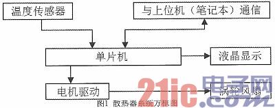
The intelligent control notebook external cooling system designed in this paper consists of a single-chip control module, a temperature sensor module, a display module, a motor drive control module, a host computer communication module and a turbine dispersed cooling module, as shown in Figure 1.
2 System Working Principle
The system obtains the ambient temperature through the temperature sensor DS18B20 and sends it to the microcontroller, and communicates with the host notebook through the microcontroller to obtain the CPU operating temperature in the computer WMI (Windows Management Instrumentation).
The working process of the three working modes: Mode 1: compare the two temperature information, when the CPU working temperature exceeds the ambient temperature by 30 degrees Celsius, start the radiator; Mode 2: when the CPU working temperature reaches 70 degrees Celsius, start the radiator; in addition, the system can be controlled by the user to force the radiator to start, so as to remove dust and cool down. Information such as system working mode, CPU working temperature and ambient temperature can be displayed on the display. When starting the radiator, the system must be controlled by the microcontroller. When the microcontroller receives the command, it outputs a PWM control signal to make the L298N drive circuit drive the rotation of the turbo fan motor.
3. Introduction to main modules
3.1 Introduction to MCU and peripheral circuits
The STM32F103xx enhanced series uses the ARM Correx-M3 32-bit RISC core, operates at 72MHz, has built-in high-speed memory (128K bytes of flash memory and 20K bytes of SRAM), enhanced I/O ports and peripherals connected to two APB buses. It includes two 12-bit ADCs, three general-purpose 16-bit timers and a PWM timer, as well as multiple communication interfaces: two I2Cs and SPIs, three USARTs, a USB and a CAN.
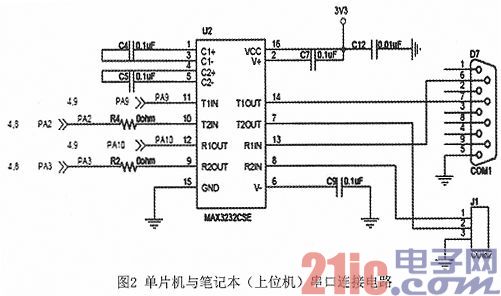
In the I/O port, GPIOA.3 is used as the DS18B20 data acquisition port. As shown in Figure 2, PA9 (USART1 TX) and PA10 (USART1 RX) are used as the host computer communication ports and are connected to the IN input and OUT output pins of the MAX232 chip respectively. Some pins of the PA, PB, PD, PE and other ports are connected to the TFT LCD screen.
3.2 Driving circuit
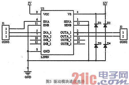
L298N is a product of SGS. It contains a 4-channel logic drive circuit. It is a dedicated driver for two-phase and four-phase motors, that is, a high-voltage and high-current dual full-bridge driver with two H-bridges. It receives standard TTL logic level signals and can drive motors below 46V and 2A. In this design, a 12V voltage is used to drive the motor, so that it can achieve higher power and enhance heat dissipation. Among them, the single-chip GPIOA.0 is connected to the L298N enable terminal ENA to control the motor rotation switch; GPIOA.1 multiplexes PWM output, connects to the L298N input terminal IN1, and the input terminal IN2 is grounded. The motor speed is controlled by changing the duty cycle of the PWM output.
4 Programming
The system has many software modules, including main program, microcontroller and notebook communication subroutine, temperature sensor module, motor drive subroutine, LCD display subroutine, etc.
4.1 Host computer program design and interface
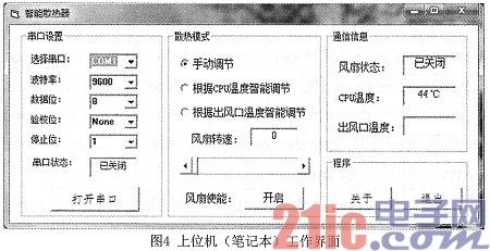
The host computer in this design is written in Visual Basic, which is an event-driven programming language developed by Microsoft that includes an auxiliary development environment. Programmers can easily use the components provided by VB to quickly build an application.
4.2 CPU temperature acquisition
WMI is the core of Windows 2K/XP management system. It is an object database that describes the components of the operating system and provides a public interface for MMC and script programs to access the components of the operating system.
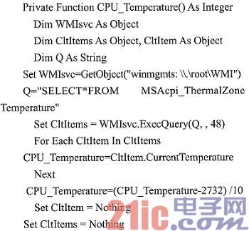
In VB, we retrieve the MSAcpi_Thermal ZoneTemperature class in WMI, find the data member CurrentTemperature, and then calculate the current CPU temperature through the formula CPU_Temperature=(CltItem.CurrentTemperature-2732)/10. However, since the data update only occurs when the computer is turned on, the CPU temperature data in WMI can be continuously refreshed by opening the SpeedFan software. In VB, we use the Timer to read the data regularly to obtain the real-time CPU temperature.
The attached procedures are as follows:
4.3 Cooling mode settings
This module design is equipped with a fan enable button and has three cooling modes: 1. Manual adjustment mode 2. Intelligent adjustment mode based on CPU temperature 3. Intelligent adjustment mode based on outlet temperature.
The fan enable button changes the fan enable bit and sends it to the microcontroller through serial communication, changing the GPIOA.0 level and then changing the L298N enable terminal level to achieve the effect of controlling the motor switch.
Three cooling modes can be switched through radio buttons: 1. Manual adjustment mode 2. Intelligent adjustment mode based on CPU temperature 3. Intelligent adjustment mode based on outlet temperature.
In manual adjustment mode, the fan speed value can be changed by pulling the scroll bar; according to the CPU temperature intelligent adjustment mode, the current CPU temperature is corresponded to the fan speed, and the fan speed value is equal to the CPU temperature value; according to the outlet air temperature intelligent adjustment mode, the temperature collected by the DS18B20 sensor is obtained, and the fan speed value is equal to the temperature multiplied by the proportional coefficient 2; the fan speed is sent to the microcontroller through the serial port and converted into a PWM duty cycle, thereby controlling the motor speed.
4.4 Serial Communication
In this design, the MSComm control in VB can be used to easily communicate with the microcontroller through the serial port. The serial port number, baud rate, data bit, check bit, and stop bit of the control can be quickly set by designing drop-down options in the VB interface. The following are several common properties involved in this design:
Commport: Set or return the serial port number.
Settings: Set or return serial port communication parameters in the form of a string.
Portopen: Set or return the serial port status.
Inputlen: Sets or returns the number of bytes read from the receive buffer at a time.
InBufferSize: Sets or returns the size of the receive buffer. The default value is 1024 bytes.
Rthreshold: This attribute is a threshold.
Output: Sends data to the send buffer. This property is invalid at design time and read-only at runtime.
Inptut: Read data from the receive buffer and clear the buffer. This property is invalid at design time and is read-only at runtime.
During program execution, the timer sends four data items to the MCU every 1 second: fan enable, cooling mode, CPU temperature, and fan speed. The MCU also sends the temperature data collected by DS18B20 to the host computer every 100ms.
4.5 PWM Output
In the design, GPIOA.1 outputs PWM wave. The steps to initialize PWM with the help of library function include:
1. Turn on the TIM2 clock and the multiplexed function clock, and configure PA1 as multiplexed output;
2. Set TIM2 CH2 to remap to PA1;
3. Initialize TIM2 and set ARR and PSC of TIM2;
4. Set the PWM mode of TIM2 CH2 and enable the CH2 output of TIM2;
5 Enable TIM2.
In this design, TIM TimeBaseStructure.TIM_Period=900;
TIM TimeBaseStructure.TIM_Prescaler=0; makes GPIOA.1 output frequency 7200/900=8Khz;
Call TIM_SetCompare2(TIM2, uint16_t Compare2) in the main function and change the Compare2 value to control the PWM output frequency.
4.6 DS18B20 Temperature Collection
DS18B20 is the latest "one-line device" of DALLAS's single-line digital temperature sensor. It is the world's first temperature sensor that supports the "one-line bus" interface. The measurement temperature range is -55℃~+125℃, and the accuracy is ±0.5℃ within the range of -10~+85℃.
When STM32 reads the temperature data from DS18B20, first enable the GPIOA.3 port clock and configure it as a push-pull output. According to the DS18B20 protocol, the microcontroller must go through the following four steps to control DS18B20 to complete the temperature conversion: DS18B20 initialization, ROM operation command, memory operation command, and data processing.
During initialization, the bus master issues a reset pulse, followed by a presence pulse from the slave device. The presence pulse lets the bus controller know that the DS1820 is on the bus and is ready for operation.
After initialization, when you need to read the temperature information in DS18B20, follow the steps below:
1. The host issues a reset operation and receives the response (presence) pulse from the DS18B20
2. The host sends a skip ROM operation command (CCH)
3. The host sends a temperature conversion operation command (44H)
4. The host issues a reset operation and receives the response (presence) pulse from the DS18B20
5. The host sends a skip ROM operation command (CCH)
6. The host issues a command to read RAM (BEH)
Read the low byte first and then the high byte. Judge the positive or negative temperature according to the highest bit of the high byte. If the highest bit is 1, the temperature is negative. Invert the two bytes. If it is 0, it remains unchanged. Then perform temperature conversion. The conversion formula is: actual temperature = (float) 16-bit data * 0.625.
Previous article:LED power drive circuit system design
Next article:Is Password Security Identity Really Safe?
- "Cross-chip" quantum entanglement helps build more powerful quantum computing capabilities
- Why is the vehicle operating system (Vehicle OS) becoming more and more important?
- Car Sensors - A detailed explanation of LiDAR
- Simple differences between automotive (ultrasonic, millimeter wave, laser) radars
- Comprehensive knowledge about automobile circuits
- Introduction of domestic automotive-grade bipolar latch Hall chip CHA44X
- Infineon Technologies and Magneti Marelli to Drive Regional Control Unit Innovation with AURIX™ TC4x MCU Family
- Power of E-band millimeter-wave radar
- Hardware design of power supply system for automobile controller
 Professor at Beihang University, dedicated to promoting microcontrollers and embedded systems for over 20 years.
- Intel promotes AI with multi-dimensional efforts in technology, application, and ecology
- ChinaJoy Qualcomm Snapdragon Theme Pavilion takes you to experience the new changes in digital entertainment in the 5G era
- Infineon's latest generation IGBT technology platform enables precise control of speed and position
- Two test methods for LED lighting life
- Don't Let Lightning Induced Surges Scare You
- Application of brushless motor controller ML4425/4426
- Easy identification of LED power supply quality
- World's first integrated photovoltaic solar system completed in Israel
- Sliding window mean filter for avr microcontroller AD conversion
- What does call mean in the detailed explanation of ABB robot programming instructions?
- STMicroelectronics discloses its 2027-2028 financial model and path to achieve its 2030 goals
- 2024 China Automotive Charging and Battery Swapping Ecosystem Conference held in Taiyuan
- State-owned enterprises team up to invest in solid-state battery giant
- The evolution of electronic and electrical architecture is accelerating
- The first! National Automotive Chip Quality Inspection Center established
- BYD releases self-developed automotive chip using 4nm process, with a running score of up to 1.15 million
- GEODNET launches GEO-PULSE, a car GPS navigation device
- Should Chinese car companies develop their own high-computing chips?
- Infineon and Siemens combine embedded automotive software platform with microcontrollers to provide the necessary functions for next-generation SDVs
- Continental launches invisible biometric sensor display to monitor passengers' vital signs
- Review summary: TI LAUNCHXL-CC1352P-4
- DE1-SOC development board usage learning
- The use of stack in DSP
- 3D printed python pen holder
- TI Smart POS System Block Diagram Analysis and Its Seven Key Functional Module Solutions
- Cubietruck dual-core A20 development board
- TI DSP simulator type selection
- Comparison between C++ Builder and VC
- When developing automotive instrument clusters for HMI, should we use algorithms or HAP?
- The display principle of the segment code screen, for example, to display the word high voltage, which two pins are driven, and high voltage is a character, isn't it...


 Introduction to Artificial Intelligence and Robotics (Murphy)


 京公网安备 11010802033920号