More and more companies are using variable speed drive engines to reduce energy consumption. This requires simplifying the design, shortening development time, and eliminating complex mathematical formulas by moving from differential (PID) controllers to systems based on fuzzy logic algorithms.
However, this presents new challenges for the motor. Controlling the speed of a brushless DC (BLDC) motor is complex when using traditional integral and differential (PID) controllers because they rely on complex mathematical models and are computationally intensive. Using fuzzy logic (FL) algorithms can eliminate the design process's reliance on complex mathematical formulas and provide an easy-to-understand solution. Another advantage of fuzzy logic (FL) engine control over (PID) differential controllers is that the development cycle is shorter. This article discusses the process of using fuzzy logic algorithms to control brushless DC motors using the Texas Instruments c28xx fixed-point DSP series.
Development of brushless DC motor control model
Before a fuzzy logic (FL) engine can be built, we must first build a model as a basis for the design. A fuzzy logic controller uses heuristic knowledge and uses a language to describe the model to express its design. Rather than developing a model from scratch, we will use the PID controller model as a starting point. Once developed and implemented, the fuzzy logic controller will be improved by adjusting its parameters.
Generally speaking, there are three design steps to develop a fuzzy logic BLDC controller:
1. Define the operating range of the input and output controllers.
2. Define the functions and rules of fuzzy membership sets.
3. Adjust the engine.
The first step is to define the model-dependent inputs and outputs. The input is the error (E), which is the current error between the set speed (SS) and the current speed (CS); the other input is the change in error (CE), which is the difference between the current error and the previously calculated error (PE). The output is the change in armature voltage (CV), which is the difference between the existing armature voltage (CAV) and the previously stored value of the armature voltage (PAV). The resulting model equation is as follows:
E=SS-CS
CE=E-PE
CV=CAV-PAV
The unit of the engine speed is revolutions per minute (RPM), and E determines the degree of approach to the target speed. Therefore, when E>0, the engine speed is lower than the set speed; when E<0, the motor speed exceeds the set speed. CE determines the adjustment direction of the controller. CE is positive if and only if (iff) the current rotation speed is lower than the set speed; CE is negative if and only if the current rotation speed is greater than the set speed. When approaching the set speed, CE will adjust back and forth between positive and negative values. CV is the supply voltage of the armature. This voltage is expressed as the pulse width modulation (PWM) duty cycle.
The next step is to define the membership functions, variables and rules for the fuzzy sets. In order for this to work, the non-fuzzy (crisp) inputs and outputs must be converted to fuzzy ones. The conversion is done by using linguistic variables to represent the input and output ranges. These are also called fuzzy variables. Fuzzy variables are used to partition the range of membership values for the membership functions. For example, five variables are used to map the inputs and outputs, which are medium negative (NM), small negative (NS), zero (z), small positive (PS), medium positive (PM).
It is not a mathematical formula, fuzzy controller uses fuzzy rules to make a decision and produce an output. Fuzzy rules are described in the form of IF-THEN statements. Fuzzy rules determine the behavior of the system instead of complex mathematical equations. For example, if the error (E) is equal to a medium negative value (NM) and the change in error (CE) is equal to a small positive value (PS), then the change in armature voltage (CV) is equal to a small negative value (NS). The number of rules used is set based on the designer's experience and knowledge of the system. Therefore, the number of rules used in our system is 25.
In order to activate the armature, the CV fuzzy output must be converted back to a sharp output. This process is called defuzzification. A popular defuzzification method is called the centroid method.
The final step of the design is to tune the membership functions and rules. This phase is also called the optimization phase. Optimization is used to improve the performance of the fuzzy controller. Once the design is complete, the controller is ready for implementation.
The implementation of the fuzzy logic controller is composed of three modules. They are fuzzification, rule deployment and defuzzification. The following sections discuss the implementation of the fuzzy logic BLDC motor related modules.
Fuzzification
Fuzzification is the process of converting data with clear numerical values into fuzzy data. The resulting fuzzy data is converted based on the fuzzy membership of the input variables. For this application, the motor control input variables are the rotation error (Error) and the rotation error difference (Cerror). The rotation error (Error) is the absolute rotation speed difference from one sampling time to the next sampling time. Similarly, the rotation error difference (Cerror) is the change in rotation error between one sampling time and the next sampling time. The formula is as follows:
Rotation error (Error) = SetSpeed (set speed) - CurrentSpeed (current speed)
Rotation error difference (Cerror) = rotation error (Error) - Previous Error (previous error)
As mentioned earlier, five member sets are defined for the rotation error (Error) variable and the rotation error difference (Cerror) variable:
1. NM: Medium Negative
2. NS: Slightly Negative
3. ZE: Zero
4. PS: Slightly Positive
5. PM: Medium Positive
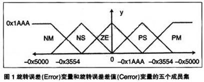
Figure 1 shows five sets of members defined for the rotation error (Error) variable and the rotation error difference (Cerror) variable. These sets are triangularly overlapped to provide a good response. Each set has a maximum value of 0×1AAA.
 [page]
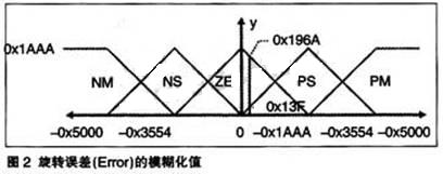
The fuzzification of the input variables produces a vector consisting of five components, which correspond to the medium negative value, small negative value, zero, small positive value, and medium positive value of the fuzzified membership set. The value of the Y axis corresponding to each component represents the membership of the explicit input value. The vector contains the rotation error (Error) and the rotation error difference (Cerror). The fuzzified values are represented as arrays ×1[] and X2[].
Figures 2 and 3 graphically show the rotation error [Error) and the rotation error difference (Cerror) fuzzy values.
Fuzzy Inference Rules
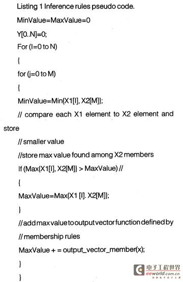
Fuzzy inference rules operate on fuzzified data to determine the behavior of the system. Specifically, the fuzzified data is applied against the rule table. In terms of language, this is the comparison of the input data Error, Cerror with the rule table. The rule table contains the member sets NM, NS, ZE, PS, and PM, and operates according to the control surface. The output is a valid "inferred" or "given" rule. The description of the inference process is shown in the following pseudo code listing:
Defuzzification
Defuzzification is the process of converting fuzzy data into crisp data. For the purpose of this application, the defuzzified value determines the duty cycle of the PWM signal used to drive the motor. The duty cycle is determined by using a modified centroid calculation function. The defuzzification method used here is to multiply the centroid calculation function by a coefficient. The modified calculation is also called the centroid calculation function. [page]
The calculation formula of the centroid is:
Defuzzified VaLue=∑-Y[i]XmultCoeff[l]/∑Y[i]
The i in Y[i] is the output vector element, which is the coefficient by which the output member set of multCoeff[i] should be multiplied. i can be 1 to 5. The result of the formula calculation is the defuzzified result.
FIG. 4 graphically shows the output member set used by the application with the coefficients [-0x10, -0x8, 0x0, 0x8, 0x10].
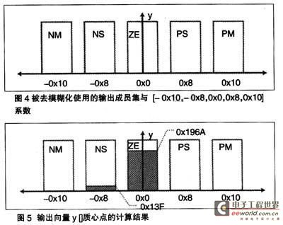
Assume that y[] = [0x0, 0x13F, 0x196A, 0x0, 0x0], then the defuzzified output value is as follows:
Defuz=0×(-16)+319×(-8)+6506×(0)+0×(8)+0×(16)/0+319+6506+0+0=-2552/6825=” -0.37391
FIG5 shows the calculation result of the centroid of the output vector y[].
Hardware Description
The eZDSP2812 board is used in this motor control application. The core of the eZdsp board is the TMS320F2812 digital signal processor. The board uses timer T1, a 20kHz clock, to generate the signals for PWM1-6, and uses timer T2 to execute the interrupt service routine (ISR). In addition, the input capture pins CAP1-3 are used to collect high-speed data from the Hall Effect sensor .
The motor is driven by PWM signals generated by the DSP. These six PWM signals are used as sources for the three-phase power converter. The power converter converts these six signals into three-phase signals and directly uses them as power sources for the motor . The function of the three-phase power converter is handled by an auxiliary motor control board . Spectrum Digital provides two boards that can provide this function: DMC550 and DMC1500. Either of them can be directly plugged into the eZdsp28xx board for use.
Hall effect sensors are used for fuzzy logic control loop feedback. The switching of the three-phase power converter is determined by detecting the signal received from the Hall effect sensor. The signal is fed into the acquisition pin of the TMS320F2812. The actual motor speed is calculated by counting through a software module.
Software Introduction
The motor control software is composed of the Digital Microcircuit (DMC) library modules and the FL motor control program. There are seven modules in the Digital Microcircuit (DMC) library that are used in this application. They are:
·Datalog data logging
·BLDC3PWM
·tall3_Drv
·Mod6_Cnt
·Rmp2Cntl
·Rarnp_Cntl
·Speed_PR
Additionally, fuzzy logic motor control is handled by one main FuzzyCtl() routine; for brushless DC motors this is Fuzzy-BLDC().
The software starts with a first run configuration followed by application specific setup. Specifically, the GPIO pins are configured as CAPture and PWM pins.
The next step is to initialize the timer and module parameters, and set the ISR. When all peripherals are set, the interrupt is activated and the main control system is entered. The main control system calls the fuzzy controller every 8.7 milliseconds.
The error values are converted into fuzzy values through fuzzification and stored in X1[] and X2[]. Once converted, the fuzzy values are applied to the fuzzy inference rules.
The result from the inference module is stored in Y[]. The output from Y[] is converted to a crisp value in the defuzzification module. The resulting crisp value is a PWM offset that is added to the current PWM duty cycle. The updated PWM value is checked to see if the new value is within a certain range, and if not, appropriate action is taken. Finally, the fuzzy controller returns the updated PWM duty cycle to the calling routine.
Figure 6 shows the demo application debugging session.
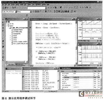
Channels 1 and 2 (in the upper right display window) show the PWM counter and the captured Hall Effect sensor, respectively. Channels 3 and 4 (below channels 1 and 2) show edge-triggered versions of the PWM counter and Hall Effect sensor display windows. The important variables are shown in the watch window, the most important of which are SetSpeed and CurrentSpeed. These values are close enough that the output of the fuzzy logic controller is zero.
This session shows the engine running under no-load conditions. The behavior may be slightly different than under load. Also, if finer granularity is desired, it may be necessary to tune the controller.
Previous article:Design of DSP-based engine controller using fuzzy logic
Next article:Software Design of Optical Fiber Pyrometer Based on DSP
Recommended ReadingLatest update time:2024-11-16 21:53


- Popular Resources
- Popular amplifiers
- Huawei's Strategic Department Director Gai Gang: The cumulative installed base of open source Euler operating system exceeds 10 million sets
- Analysis of the application of several common contact parts in high-voltage connectors of new energy vehicles
- Wiring harness durability test and contact voltage drop test method
- Sn-doped CuO nanostructure-based ethanol gas sensor for real-time drunk driving detection in vehicles
- Design considerations for automotive battery wiring harness
- Do you know all the various motors commonly used in automotive electronics?
- What are the functions of the Internet of Vehicles? What are the uses and benefits of the Internet of Vehicles?
- Power Inverter - A critical safety system for electric vehicles
- Analysis of the information security mechanism of AUTOSAR, the automotive embedded software framework
 Professor at Beihang University, dedicated to promoting microcontrollers and embedded systems for over 20 years.
- Innolux's intelligent steer-by-wire solution makes cars smarter and safer
- 8051 MCU - Parity Check
- How to efficiently balance the sensitivity of tactile sensing interfaces
- What should I do if the servo motor shakes? What causes the servo motor to shake quickly?
- 【Brushless Motor】Analysis of three-phase BLDC motor and sharing of two popular development boards
- Midea Industrial Technology's subsidiaries Clou Electronics and Hekang New Energy jointly appeared at the Munich Battery Energy Storage Exhibition and Solar Energy Exhibition
- Guoxin Sichen | Application of ferroelectric memory PB85RS2MC in power battery management, with a capacity of 2M
- Analysis of common faults of frequency converter
- In a head-on competition with Qualcomm, what kind of cockpit products has Intel come up with?
- Dalian Rongke's all-vanadium liquid flow battery energy storage equipment industrialization project has entered the sprint stage before production
- Allegro MicroSystems Introduces Advanced Magnetic and Inductive Position Sensing Solutions at Electronica 2024
- Car key in the left hand, liveness detection radar in the right hand, UWB is imperative for cars!
- After a decade of rapid development, domestic CIS has entered the market
- Aegis Dagger Battery + Thor EM-i Super Hybrid, Geely New Energy has thrown out two "king bombs"
- A brief discussion on functional safety - fault, error, and failure
- In the smart car 2.0 cycle, these core industry chains are facing major opportunities!
- The United States and Japan are developing new batteries. CATL faces challenges? How should China's new energy battery industry respond?
- Murata launches high-precision 6-axis inertial sensor for automobiles
- Ford patents pre-charge alarm to help save costs and respond to emergencies
- New real-time microcontroller system from Texas Instruments enables smarter processing in automotive and industrial applications
- Voltage jump problem
- 【Silicon Labs Development Kit Review】1-Introduction to Main Components
- MCU Basics: Detailed explanation of button single click, double click, and long press
- 【McQueen Trial】Main functions corresponding to driver pins
- ti dsp (tms320VC5502) + isp1581 usb2.0 high speed data acquisition solution
- [Problem Feedback] Anlu TD4.6.6-64bit pin constraint input PIN number bank does not automatically update the problem
- Tesla's electric motor
- Design of prison security system by integrating wireless sensors with control network
- Fast charging knowledge sharing: PD protocol fast charging
- [Voice Recognition Positioning] Material Unboxing-ESP32-S2-KALUGA-1

 MATLAB and FPGA implementation of wireless communication


 京公网安备 11010802033920号