Introduction


Keywords:TMS320C6678 VLFFT DSP TI SoC
Reference address:VLFFT Demonstration for TMS320C6678 Processor
This white paper discusses the VLFFT demonstration of the TMS320C6678 processor. The TMS320C6678 processor with eight fixed and floating point DSP cores is used to execute 16K-1024K samples of a one-dimensional single precision floating point FFT algorithm and the runtime is measured when using 1, 2, 4 or 8 cores. The results of the demonstration demonstrate the excellent performance of the C66X DSP cores and the parallel execution performance of the TMS320C6678 processor across multiple cores is proportional to the number of cores. The demonstration uses the FFT algorithm, which is frequently used in fields such as medical imaging, communications, military and commercial radar, and electronic warfare (jammers, anti-jammers). The demonstration results show that the TMS320C6678 processor only takes 6.4 milliseconds to execute 1024K samples of the FFT algorithm when running at 1 GHz and 8 DSP cores.
TMS320C6678 SoC
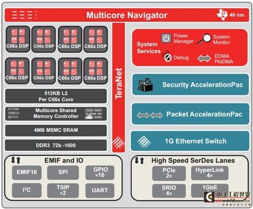
The TMS320C6678 processor has eight DSP cores and is based on TI's C66x fixed and floating-point DSP cores and TI's innovative KeyStone architecture, which has multi-core rights. It runs at up to 1.25GHz, at which speed it can perform 160 gigaflops of floating-point operations per second, and typically consumes less than 10w of power. The TMS320C6678 processor features 512KB of L2 memory for each DSP core; in addition, there is 4MB of shared memory in the 8MB chip memory, and both memories have error correction codes. Its DDR3 interface is 64-bit, has 8-bit error correction codes, runs at speeds of up to 1600 megabits per second, and supports up to 8GB of external memory data access. In addition, TMS320C6678's peripherals include PCle, Serial RapidIO®, Gigabit Ethernet and TI's HyperLink interface, which can provide connection speeds of up to 50Gbps when connected to TI's other DSP, ARM, ARM+DSP processors and third-party FPGAs.
In this article's VLFFT demonstration, the TMS320C6678 processor runs at 1GHz and the DDR3 interface transfers at 1333MHz.

Figure 1 TMS320C6678 block diagram
VLFFT Demo
Since the VLFFT algorithm requires the input data to be stored in the processor's external memory, in this demonstration, the data is accessed, distributed, and processed by the DSP core, and the results are finally output to the external memory. At the same time, the cycle count and time measurement are always maintained throughout the process. During the demonstration, different numbers of cores (1, 2, 4, or 8) are configured for the TMS320C6678 processor to calculate the results when the FFT size is different. These FFT specifications include:
16K
32K
64K
128K
156K
512K
1024K
During the demonstration, the maximum performance of FFT execution is ensured by distributing the computational load to multiple cores and fully utilizing the high-performance computing capabilities of the C66X DSP core. At the same time, the basic time extraction algorithm is used to express the one-dimensional VLFFT algorithm with a similar two-dimensional FFT algorithm. This method is to decompose into the form of N=N1*N2 when encountering very large data N. In this demonstration, if the one-dimensional input array is very large, it is represented by a two-dimensional array of N1 rows * N2 columns, and then the FFT is calculated by the following steps:
1. Calculate the FFT of the N2-column array when the N1-row array has different sizes;
2. Multiply by the rotation factor;
3. Store the results of the FFT algorithm when N2 columns are of different sizes in N1 rows, forming a two-dimensional array of size N2*N1;
4. Calculate the FFT of the N1 row array when the N2 column array has different sizes;
5. The data in the column direction is stored to form a two-dimensional array of N2*N1.
This algorithm is called the high-performance parallel FFT algorithm for Hitachi SR8000 by Takahashi.
When executing a multi-core algorithm, the first step is to calculate the FFT algorithm with N2 columns (number of cores) in N1 rows, and the fourth step is to calculate the FFT algorithm with N1 rows (number of cores) in N2 columns. Core 0 is the master core and is responsible for synchronization with all remaining satellite cores. Based on the size of the N1 array and the N2 array, the total FFT calculated by each core is divided into several smaller modules to fit the space of each core's L2 SRAM memory. Each set of data is pre-fetched into the L2 SRAM memory through the DMA in the external memory, and then the data is returned to the external memory through DDR. Each core uses 2 DMA channels to convert input and output data between the external memory (DDR3) and the internal memory (L2 SRAM).
result
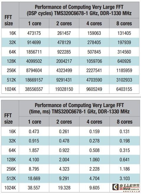
Figure 1 on the next page shows the results of running the FFT code in one DSP cycle and one millisecond for the TMS320C6678 evaluation board (TMS320C6678LE). Ideally, when the number of cores used for calculations is doubled, the cycle count will be reduced by half. However, in reality, this is difficult to achieve due to the ceiling of information operation and the limitations of memory size and information width (internal memory). In this case, when replacing a single core with dual cores, the time to run the FFT is reduced by an average of 49.3%, which is basically half of the ideal number of cycles. When replacing a single core with four cores, the time to run the FFT is reduced by an average of 72.5%, and the average operation time is reduced by 81.6% when using eight cores.

Table 1: FFT results at 1/2/4/8 DSP core cycles and milliseconds
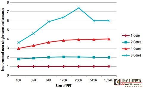
From this we can see that for both dual-core and quad-core, as the FFT size increases from 16k to 256k, the run time decreases more and more, and the run time decreases even more dramatically when using eight cores. This is because for smaller FFTs, the cost of parallel code is much smaller than the performance improvement of additional cores with more cores. Previously, the performance improvement of 256KB FFT was not very ideal, only 2 times with dual-core, 4 times with quad-core, and even reduced with eight cores. This is because the speed at which the eight cores process data is much faster than the speed at which the external memory can transfer data, causing its storage space to reach the upper limit. In this demonstration, a 1024k FFT, i.e., a one-million-point FFT, was calculated in only 6.4 milliseconds when using 8 DSP cores and running at 1GHz.

Figure 2: Performance improvement between single-core and multi-core
in conclusion
In summary, using TI's TMS320C6678 processor to perform a million-point FFT, at a frequency of 1GHz, the time required for 8 cores to run simultaneously is only 6.4 milliseconds. Such a high-speed DSP core is fully sufficient to perform real-time operations for certain applications, such as radar, electronic warfare, and medical mapping. If the TMS320C6678 processor is run at a maximum speed of 1.25GHz, and a higher bandwidth DDR3 and 1600MTPS are used, the time required to perform the operation will be even shorter.
Previous article:FPGA+CPU: Parallel processing is popular
Next article:Cadence Releases Complete Digital and Signoff Reference Flow
- Popular Resources
- Popular amplifiers
Recommended Content
Latest Embedded Articles
- Why is the vehicle operating system (Vehicle OS) becoming more and more important?
- Car Sensors - A detailed explanation of LiDAR
- Simple differences between automotive (ultrasonic, millimeter wave, laser) radars
- Comprehensive knowledge about automobile circuits
- Introduction of domestic automotive-grade bipolar latch Hall chip CHA44X
- Infineon Technologies and Magneti Marelli to Drive Regional Control Unit Innovation with AURIX™ TC4x MCU Family
- Power of E-band millimeter-wave radar
- Hardware design of power supply system for automobile controller
- Driving Automation Safety and Economic Engineering
He Limin Column
Microcontroller and Embedded Systems Bible
 Professor at Beihang University, dedicated to promoting microcontrollers and embedded systems for over 20 years.
MoreSelected Circuit Diagrams
MorePopular Articles
- Intel promotes AI with multi-dimensional efforts in technology, application, and ecology
- ChinaJoy Qualcomm Snapdragon Theme Pavilion takes you to experience the new changes in digital entertainment in the 5G era
- Infineon's latest generation IGBT technology platform enables precise control of speed and position
- Two test methods for LED lighting life
- Don't Let Lightning Induced Surges Scare You
- Application of brushless motor controller ML4425/4426
- Easy identification of LED power supply quality
- World's first integrated photovoltaic solar system completed in Israel
- Sliding window mean filter for avr microcontroller AD conversion
- What does call mean in the detailed explanation of ABB robot programming instructions?
MoreDaily News
- Breaking through the intelligent competition, Changan Automobile opens the "God's perspective"
- The world's first fully digital chassis, looking forward to the debut of the U7 PHEV and EV versions
- Design of automotive LIN communication simulator based on Renesas MCU
- When will solid-state batteries become popular?
- Adding solid-state batteries, CATL wants to continue to be the "King of Ning"
- The agency predicts that my country's public electric vehicle charging piles will reach 3.6 million this year, accounting for nearly 70% of the world
- U.S. senators urge NHTSA to issue new vehicle safety rules
- Giants step up investment, accelerating the application of solid-state batteries
- Guangzhou Auto Show: End-to-end competition accelerates, autonomous driving fully impacts luxury...
- Lotus launches ultra-900V hybrid technology "Luyao" to accelerate the "Win26" plan
Guess you like
- Verify the PEDOMER (pedometer) function through the APP
- Online text and code difference comparison tool
- Please, please take a look at this. A beginner can't do it at all.
- Digital EDA environment construction based on CentOS
- How to prevent bad phenomena of crystal oscillator
- What is the difference between an ordinary programmer and a senior programmer?
- How does a digital multimeter measure voltage, current, resistance, capacitance, diode, and transistor?
- Oscilloscope measuring the waveform of BYD Qin's three-phase drive motor
- Development and application prospects of microwave power device materials
- C5000 compiles SUBC instruction to implement division


 IDT70V3599S133BCI


 京公网安备 11010802033920号