Since experience is not easy to describe accurately, various signals and evaluation indicators in the control process are not easy to express quantitatively, fuzzy theory is the best way to solve this problem. Using fuzzy control rules, DSP uses fuzzy reasoning according to the actual response of the electronic load system to achieve automatic adjustment of PID parameters, which is fuzzy adaptive PID control. With error e and ec as input, according to the change of deviation e and deviation change rate ec, fuzzy control rules are used to modify PID parameters online.

The three parameters in the PID controller are continuously adjusted to meet the requirements of PID parameter self-tuning at different times. Its mechanism is shown in Figure 4.7.
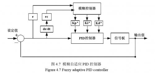
Since the designed electronic load only uses two parameters, P and I, in this study, e and ec are continuously detected during operation, fuzzy rules are used for fuzzy reasoning, and the two parameters P and I are modified online, so that the controlled object has good dynamic and static performance.
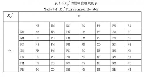
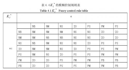
The core of fuzzy control design is to summarize the technical knowledge and practical experience of the commissioning personnel, select the input and output variables of the fuzzy controller according to the requirements of the site and the actual situation of the controlled object, select the domain and membership function of the variables, establish a suitable fuzzy rule table, and adjust the parameters after defuzzification by querying the fuzzy matrix table. The fuzzy rule tables of Kp and KI are shown in Table 4.3 and Table 4.4.
(1) Domain of input/output variables In the electronic load control system, the load current value deviation e and the deviation change rate ec (taking the constant current high position as an example) have actual domains (basic domains) of
The setting value is 6A, the basic domain of the deviation value e is (-0.04, 0.04), and the basic domain of the deviation change rate ec is (-1, 1). The basic domain of the control quantity is (-1, 1). The basic domain of the control quantity is
The choices of its basic domain (obtained based on empirical values) are: K*P∈(-0.035, 0.035) and K*I∈(-1.35, 1.35).
When selecting the domain of fuzzy variables, we must consider that each fuzzy subset can cover the domain well, prevent the loss of control, and at the same time, we cannot arbitrarily increase the number of elements in the domain. If there are too many elements in the domain, although the control accuracy of the system is improved, the workload of DSP is greatly increased, which may cause the system to run too slowly. Therefore, when selecting a specific fuzzy variable domain, we must take into account the coverage of the domain and the computing power of DSP. Its actual value in this system is (-6, -5...0, 1,...6) thirteen levels.
(2) Quantization factor and scaling factor
Each sampling value obtained by the control system needs to be multiplied by a corresponding factor so that the input variable can be converted from its actual domain to the fuzzy domain. This is the concept of the quantization factor K. Generally, Ke and Kec are used to represent the quantization factors of the system deviation e and the rate of change of the deviation ec, respectively. According to the above, the actual domains of the current deviation e and the rate of change of the deviation ec are (-|emax|, |emax|) and (-|ecmax|, |ecmax|), respectively. The fuzzy domains of all variables are the same (-n, -n+1, ...0, 1, ...n). Then, Ke and Kec can be determined by the following formula, namely:

The output obtained by fuzzy reasoning cannot directly act on the controlled object and must be converted into the basic domain recognized by the controlled object through the defuzzification interface. From the above, we can know that the basic domain of the system control quantity is

Then its proportional factors Kup and Kui are:
After obtaining the proportional factor, any actual control value that is ultimately output to the controlled object can be obtained by the following formula:
Among them, K*P and K*I represent the adjustment factors of the fuzzy controller's final output to the PID controller parameters.
According to the formulas and data given above, the quantization factor and proportional factor of this system can be calculated respectively, Ke = 150, Kec = 6, Kcp = 0.006, Kui = 0.225. The input e and ec quantization tables are shown in Table 4.1 below.

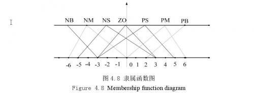
(3) The fuzzy subsets of the knowledge base input and output variables are selected as: negative large, negative medium, negative small, zero, positive small, positive medium, positive large (NB, NM, NS, ZO, PS, PM, PB). After the fuzzy language variables are determined, the membership function of each variable is selected. Generally, the membership function includes triangle, Gaussian, trapezoidal, etc. For the selection of membership function, there is no complete conclusion to explain which membership function is the best for which control object. Therefore, the selection of membership function is generally based on experience or from the perspective of calculation simplicity. The membership functions of the error and error change rate input and PID parameter output variables are all selected as triangular membership functions, and the following membership function diagram 4.8 is used uniformly. The membership
function table of each variable can be easily calculated by calculating the linear equation of the triangle from the membership function table as shown in Figure 4.8.
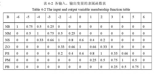
As shown in Table 4.2, "B" represents any input or output variable. The fuzzy language value of the input variable that has been converted into the fuzzy domain can be directly obtained by using this membership function table.
The role of the rule base is to store all fuzzy control rules and provide control rules for the "inference engine" when making inferences. The rule base of the fuzzy controller is a language representation based on expert knowledge and the long-term experience accumulated by manual operators, and is formed according to human intuitive reasoning. Fuzzy rules are generally connected by a series of conjunctions, such as if-then, else, also, end, or, etc. The conjunctions must be "translated" to digitize the fuzzy rules. The following principles should be followed when establishing fuzzy control rules.
a. When the system is just put into operation, the deviation e is large. In order to improve the system response speed, a larger proportional value must be taken, that is, the fuzzy controller outputs a larger K*P. At the same time, the differential action of the system should be reduced to prevent the differential saturation of the system, that is, the fuzzy controller outputs a smaller K*i.
b. When e*ec>0. At this time, the deviation changes in the direction of increasing absolute value. When the system is in the following state (e and ec are of moderate size), the fuzzy controller should output a smaller K*P and a medium-sized K*i. If the absolute deviation is large at this time, the proportional value should be increased and the integral effect should be reduced, that is, stronger control measures should be taken on the system to change the direction of error change. If the absolute deviation is small, it means that the deviation of the system is not large. The main purpose of control at this time is to eliminate static error and prevent oscillation. Therefore, the proportional value takes a moderate value to enhance the integral effect.
c. e*ecAt this time, the deviation e and its change rate ec are in the opposite direction, indicating that the system deviation changes in the direction of decreasing absolute value. When the absolute deviation is small, reduce the proportional value, eliminate static error, prevent overshoot, and make the system obtain good dynamic performance. If the absolute deviation is large, the proportional value should be appropriately increased to improve the response speed of the system. Take a smaller integral value to ensure the steady-state performance of the system.
Combining the above analysis results with the actual operation experience of the electronic load control system and describing it in fuzzy language, we can form the following fuzzy rule table of K*P and K*i, see Table 4.3 and Table 4.4.
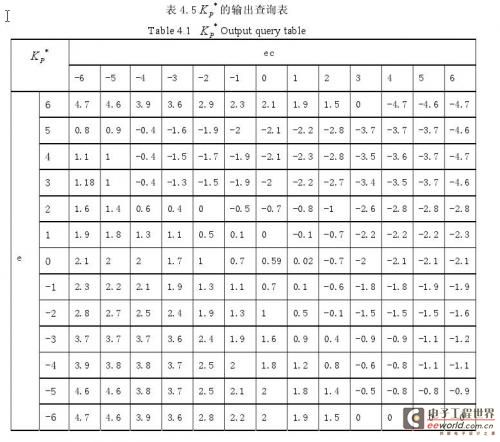
After obtaining the fuzzy control rule table, the fuzzy control output query table can be directly obtained in the fuzzy control box in MATLAB through the Ma Danni fuzzy reasoning method and the weighted average method (defuzzification method), as shown in Table 4.5. The fuzzy matrix table of PID parameters is designed according to fuzzy synthesis reasoning, and the DSP table lookup operation is used to adjust the PID online. The initial PI parameter values are set to K'P = 0.6, K'I = 2.7. This article only gives Table 4.5, which is the fuzzy output response table of K*P, and K*i is generated by the MATLAB dynamic simulation toolbox.
final
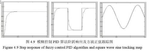
The step response and sinusoidal tracking test simulation of the electronic load model is performed using M language in MATLAB as shown in 4.9.
Previous article:Power Line Carrier OFDM Modem Based on DSP
Next article:PID Control of Electronic Throttle Based on DSP
Recommended ReadingLatest update time:2024-11-23 10:34


- Popular Resources
- Popular amplifiers
- "Cross-chip" quantum entanglement helps build more powerful quantum computing capabilities
- Why is the vehicle operating system (Vehicle OS) becoming more and more important?
- Car Sensors - A detailed explanation of LiDAR
- Simple differences between automotive (ultrasonic, millimeter wave, laser) radars
- Comprehensive knowledge about automobile circuits
- Introduction of domestic automotive-grade bipolar latch Hall chip CHA44X
- Infineon Technologies and Magneti Marelli to Drive Regional Control Unit Innovation with AURIX™ TC4x MCU Family
- Power of E-band millimeter-wave radar
- Hardware design of power supply system for automobile controller
 Professor at Beihang University, dedicated to promoting microcontrollers and embedded systems for over 20 years.
- Intel promotes AI with multi-dimensional efforts in technology, application, and ecology
- ChinaJoy Qualcomm Snapdragon Theme Pavilion takes you to experience the new changes in digital entertainment in the 5G era
- Infineon's latest generation IGBT technology platform enables precise control of speed and position
- Two test methods for LED lighting life
- Don't Let Lightning Induced Surges Scare You
- Application of brushless motor controller ML4425/4426
- Easy identification of LED power supply quality
- World's first integrated photovoltaic solar system completed in Israel
- Sliding window mean filter for avr microcontroller AD conversion
- What does call mean in the detailed explanation of ABB robot programming instructions?
- STMicroelectronics discloses its 2027-2028 financial model and path to achieve its 2030 goals
- 2024 China Automotive Charging and Battery Swapping Ecosystem Conference held in Taiyuan
- State-owned enterprises team up to invest in solid-state battery giant
- The evolution of electronic and electrical architecture is accelerating
- The first! National Automotive Chip Quality Inspection Center established
- BYD releases self-developed automotive chip using 4nm process, with a running score of up to 1.15 million
- GEODNET launches GEO-PULSE, a car GPS navigation device
- Should Chinese car companies develop their own high-computing chips?
- Infineon and Siemens combine embedded automotive software platform with microcontrollers to provide the necessary functions for next-generation SDVs
- Continental launches invisible biometric sensor display to monitor passengers' vital signs
- Happy big kids, happy Children's Day! Moderators, please go to the forum to get a small gift for Children's Day~~~~
- Crystal Filter
- Foreign open source-programmable desktop power supply EEZ H24005 design
- TI serial port problem
- Small power switching power supply design practice
- Use of I2C of TMS570LS1224
- PLC ladder diagram visual editing and automatic generation of statement table
- Qorvo Online Design Conference - How Antenna Evolution Supports 5G Mobile Devices
- Audio Hardware Basics
- How to build a "full-power" chip

 MATLAB and FPGA implementation of wireless communication


 京公网安备 11010802033920号