As a complex of high-tech, intelligent robots directly reflect the development level of a country's information technology and have been highly valued by all sectors of society. Intelligent robots involve almost all the contents of information technology, allowing students to access and see the full view of information technology. In addition, intelligent robots are an open platform for information technology. Students can give full play to their imagination to develop various intelligent devices, thereby cultivating students' ability to develop information technology. In the process of development, various abilities are cultivated and students' interest is stimulated.
This paper designs an educational robot hardware platform based on TMS320LF2407A with an intelligent car as the carrier, including the circuit design of the power module and the motor drive module, and integrates infrared and photosensitive sensors and wireless data transmission modules. Through software design, it can realize the functions of tracking, obstacle avoidance and the combination of tracking and obstacle avoidance, achieving the purpose of combining theoretical course learning with hands-on practice, consolidating knowledge and further enhancing learners' interest.
1 Design concept and overall plan
1.1 Design ideas of educational robots
This educational robot is based on the TMS320LF2407A microcontroller. It uses the external environment information collected by various sensors such as infrared sensors and photoelectric sensors as input signals, processes them through DSP, and uses PWM technology to output in real time to adjust the speed and direction of the car, so as to realize the functions of automatic control such as tracking, obstacle avoidance, tracking and obstacle avoidance. In addition, when the car is tracking, the robot can automatically
If an obstacle is encountered during the process, and the tracking and obstacle avoidance algorithm cannot complete the obstacle avoidance function while tracking, the wireless communication transceiver module connected to the PC and another wireless transceiver module connected to the DSP can realize wireless short-range communication to control the car to leave the obstacle area and perform normal tracking.
1.2 Overall design and block diagram
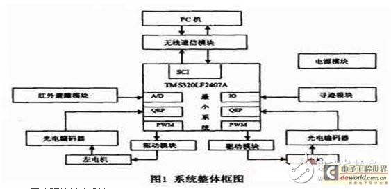
The overall block diagram of the robot car system is shown in Figure 1. It mainly consists of the TMS320LF2407A minimum system part, power module, motor drive module, sensor module, and wireless communication module. Various on-board sensors continuously transmit information to the on-board microcontroller, and download the programming design algorithm to the microcontroller to adjust the motion state of the car in real time to meet certain functional requirements.
2 System Hardware Module Design
2.1 TMS320LF2407A minimum system design
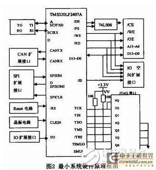
TMS320LF2407A is the most widely used product in the 2000 series. It not only has an efficient processor suitable for digital signal processing, but also integrates memory and rich on-chip peripherals suitable for control applications, thus forming a basic on-chip computer system. In addition to the advantages of improved Harvard structure, multi-bus structure and pipeline structure, it also adopts high-performance static CMOS technology, the voltage is reduced to 3.3V, the power consumption is reduced, the instruction execution speed is increased to 40MIPS, and almost all instructions can be completed within a single cycle of 2 5ns. The basic structure of TMS320LF2407A includes three components: central processing unit (CPU), memory, on-chip peripherals and dedicated hardware circuits. The hardware platform of this system fully utilizes the characteristics of TMS320LF2407A controller and adopts modular design, which is divided into basic circuit and extended control circuit. The basic circuit includes power supply circuit, reset circuit, clock circuit, A/D input channel and JTAG simulation circuit. The expansion circuit includes memory and decoding circuit, serial communication SCI and RS-232 interface circuit, CAN interface circuit, SPI functional module, etc. The system hardware principle block diagram is shown in Figure 2.
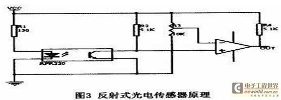
This part uses photoelectric sensors to identify road information. RPR220 photoelectric tube is used. RPR220 is an integrated reflective photoelectric detector. Its transmitter is a gallium arsenide infrared light-emitting diode, and the receiving tube is a high-sensitivity silicon planar photoelectric triode. Three infrared tubes are arranged in a "one" shape at the bottom of the front of the car. The path trajectory is indicated by the black line. According to the difference between the intensity of the reflected light received by the photoelectric triode falling in the black line area and the white area, the position of the black line photoelectric tube detected is used to judge the position and direction of the car to see whether it deviates from the black line. When the infrared diode of the infrared tube emits infrared light, it is reflected to the receiving tube by the reflector (white line), and the resistance between the collector and emitter of the receiving tube becomes smaller, the input potential becomes lower, and the output is low after comparison by the comparator. When the infrared light is irradiated on the black line, the brightness reflected on the receiving tube decreases, and the resistance between the collector and emitter of the receiving tube increases, so that the output is high. The output signal is sent to 2407A for analysis and processing. The principle of the reflective photoelectric sensor is shown in Figure 3. If the middle sensor (center sensor) detects a black line, the sensor will send a "wired" signal, and the two rear wheel motors will continue to run, driving the vehicle forward. If any of the left and right sensors, except the center sensor, does not detect a black line, the sensor will output a "wireless" signal, and the drive motor on the opposite side of the sensor that has left the guide line will stop running, while the motor on the same side will continue to run, thereby achieving the purpose of correcting the direction of travel.
2.3 Design of infrared obstacle avoidance module
When the car encounters an obstacle during its movement and cannot pass through normally, an infrared detector is used to detect the obstacle, and an algorithm is designed to control the car to bypass the obstacle and continue to track forward. An infrared emitting diode (such as Toshiba TLN110) is installed on both sides of the front end of the car to transmit infrared signals. The signal emitted by the infrared light source is modulated to 38kHz, and the PWM output of 2407A is used to generate accurate signals. The infrared receiver receives the infrared signal by a dedicated infrared receiving module (such as CRVPl738) installed in the center of the car head. The principle of judging obstacles in the car's forward route: a. The infrared emitting diode on the left transmits a signal, detects the central receiving end, and determines whether the signal is received; b. The infrared emitting diode on the right transmits a signal, detects the central receiving end, and determines whether the signal is received; c. If there is a signal received when the left side is transmitted, there is an obstacle on the left side of the car; if there is a signal received when the right side is transmitted, there is an obstacle on the right side of the car; if there is a signal received when both the left and right sides are transmitted, there is an obstacle directly in front of the car.
There are three obstacle avoidance algorithms when the car moves forward: walking along the left side, walking along the right side, and walking in combination with the left and right sides. This design aims to avoid obstacles in a variety of environments, so the algorithm of walking in combination with the left and right sides is selected. Several infrared distance measuring sensors (GP2D12) are installed on the left and right sides of the car in equal proportion to prevent the car from colliding with obstacles during obstacle avoidance. Since the output of GP2-D12 is an analog signal of 0.4~2.4V, corresponding to a distance of 80~10cm, the output is inversely proportional to the distance and is nonlinear. The A/D conversion function integrated in 2407A can be directly used to perform A/D conversion to obtain the corresponding parameters. According to the parameters, the DSP performs corresponding processing to avoid obstacles and move forward. In the process of obstacle avoidance, a proximity control strategy is adopted to maintain the distance between the obstacle and the sensor as a fixed constant. When the distance between the two is small, the robot rotates in the direction away from the obstacle; when the distance between the two is large, it rotates in the direction close to the obstacle. When the car moves along the obstacle, when the photoelectric sensor at the bottom of the front of the car detects a black line, the car begins to adjust its moving posture, stay away from the obstacle, and continue to track. In addition, when the car cannot successfully bypass the obstacle to continue tracking, the wireless communication module can be used to control the car to bypass the obstacle to continue tracking.
2.4 Wireless Communication Module Design
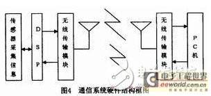
In the case that the robot cannot successfully avoid obstacles, the obstacle avoidance task can be completed through the communication cooperation between the DSP and the host computer (PC). The communication methods between the DSP and the PC are divided into wired and wireless, and most of them use serial communication. In this design, wireless communication is used to overcome the inconvenience caused by wired communication. PTR2000 is a wireless data transmission module based on the nRF401 device. It has the characteristics of low-frequency transmission and high sensitivity, which makes it widely used in embedded short-range wireless products. To achieve wireless communication between the DSP and the PC, a PTR2000 device needs to be installed on the DSP and the car body respectively. The system hardware structure block diagram is shown in Figure 4. The connection between PTR2000 and DSP is completed by directly connecting the RXD and TXD pins of 2407A with the DO and DI pins of PTR2000, and the control pin of 2407A is connected to the mode control pin of PTR2000. The connection between PTR2000 and DSP is completed by using the MAX232 device to convert between RS-232 and TTL levels between PTR2000 and the computer serial port, and then the connection between PTR2000 and the PC serial port is completed. The DSP and PC software work together to set the status of PTR2000 (transmit or receive), select a fixed communication channel, and keep PTR2000 in normal working state, and then realize the wireless communication function by designing the software system.
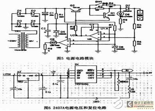
The power module can be charged by a 16V AC voltage charger through a power charging circuit for 6 car-mounted nickel-cadmium batteries (about 7.2V) to provide working voltage for each module. The power circuit module is shown in Figure 5. Since the working voltage required by each module is different, a 5V DC voltage can be obtained by using a 78 (L) 05 regulator. The 3.3V power supply required by 2407A is realized by a low-voltage dropout regulator TPS733Q with an integrated delayed reset function, which also has a reset function. As shown in Figure 5.
2.6 Motor drive module design
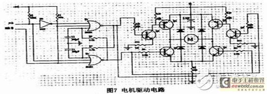
This wheeled robot platform is driven by left and right DC motors, with a universal wheel in the middle for support. The motor drive module can realize the rotation of the two motors in any direction to achieve the purpose of the car moving forward, backward and turning. Whether the motor turns or not is determined by the sequence of high and low voltage signals provided to the motor drive circuit, which comes from the digital logic gate sequencing circuit at the front end. The input signal of the digital logic sequencing circuit is the direction signal and PWM signal generated by 2407A to realize the control of the direction and speed of the robot. It is divided into the direction end and the enable end. The circuit can also avoid the damage to electronic devices caused by power short circuit. This car motor drive circuit is an H-bridge drive circuit, which controls the direction of the motor current flow. When Q1 and 04 are turned on, the motor current flows from left to right and the motor rotates forward; when Q2 and Q3 are turned on, the motor current flows from right to left and the motor reverses. As shown in Figure 7.
3 Overall system implementation
The overall function of the educational robot hardware system with TMS320LF2407A as the core can be simulated and debugged by mixed programming of C language and assembly language under the support of software development tool CCS and hardware development tool XDS, and then downloaded to DSP through JTAG interface for implementation, which brings great convenience to DSP learners. At the same time, thanks to the richness of 2407A external resources, the unused parts of the system are conducive to learners to do further function development and application.
4 Conclusion
The overall hardware system has a simple structure and good scalability. It can control the robot to complete certain functions through software programming, which can well exercise students' logical thinking ability and programming ability, and help cultivate students' practical ability.
Previous article:DSP in FPGA: FIR Filter (Part 2)
Next article:A visual system design based on service robot
Recommended ReadingLatest update time:2024-11-16 14:52


- Popular Resources
- Popular amplifiers
- Huawei's Strategic Department Director Gai Gang: The cumulative installed base of open source Euler operating system exceeds 10 million sets
- Analysis of the application of several common contact parts in high-voltage connectors of new energy vehicles
- Wiring harness durability test and contact voltage drop test method
- Sn-doped CuO nanostructure-based ethanol gas sensor for real-time drunk driving detection in vehicles
- Design considerations for automotive battery wiring harness
- Do you know all the various motors commonly used in automotive electronics?
- What are the functions of the Internet of Vehicles? What are the uses and benefits of the Internet of Vehicles?
- Power Inverter - A critical safety system for electric vehicles
- Analysis of the information security mechanism of AUTOSAR, the automotive embedded software framework
 Professor at Beihang University, dedicated to promoting microcontrollers and embedded systems for over 20 years.
- Innolux's intelligent steer-by-wire solution makes cars smarter and safer
- 8051 MCU - Parity Check
- How to efficiently balance the sensitivity of tactile sensing interfaces
- What should I do if the servo motor shakes? What causes the servo motor to shake quickly?
- 【Brushless Motor】Analysis of three-phase BLDC motor and sharing of two popular development boards
- Midea Industrial Technology's subsidiaries Clou Electronics and Hekang New Energy jointly appeared at the Munich Battery Energy Storage Exhibition and Solar Energy Exhibition
- Guoxin Sichen | Application of ferroelectric memory PB85RS2MC in power battery management, with a capacity of 2M
- Analysis of common faults of frequency converter
- In a head-on competition with Qualcomm, what kind of cockpit products has Intel come up with?
- Dalian Rongke's all-vanadium liquid flow battery energy storage equipment industrialization project has entered the sprint stage before production
- Allegro MicroSystems Introduces Advanced Magnetic and Inductive Position Sensing Solutions at Electronica 2024
- Car key in the left hand, liveness detection radar in the right hand, UWB is imperative for cars!
- After a decade of rapid development, domestic CIS has entered the market
- Aegis Dagger Battery + Thor EM-i Super Hybrid, Geely New Energy has thrown out two "king bombs"
- A brief discussion on functional safety - fault, error, and failure
- In the smart car 2.0 cycle, these core industry chains are facing major opportunities!
- The United States and Japan are developing new batteries. CATL faces challenges? How should China's new energy battery industry respond?
- Murata launches high-precision 6-axis inertial sensor for automobiles
- Ford patents pre-charge alarm to help save costs and respond to emergencies
- New real-time microcontroller system from Texas Instruments enables smarter processing in automotive and industrial applications
- EEWORLD University Hall ---- Digital Signal Processing Beihang Wang Jun
- Application analysis of CC1310 low power consumption advantage
- I am currently using powerSTEP01 to drive a 86mm stepper motor. Does anyone have a driver for this chip?
- C6000 Program Optimization Process and Method
- "Analog input signal" protection circuit
- Simple---a TMS320F28035 key driver
- Reference Design for EtherCAT Slave without DDR
- Crystal Oscillator PPM Small Parameters, Big Effect
- About BL9341DC24V-3.3V
- BQ25619 is a charging chip suitable for headphones

 MATLAB and FPGA implementation of wireless communication


 京公网安备 11010802033920号