Active suspension is a type of automotive suspension on a vehicle. It uses an on-board system to control the vertical movement of the wheels relative to the chassis or body, rather than passive suspension provided by large springs, where movement is entirely determined by the road surface. Active suspensions fall into two categories: true active suspension and adaptive or semi-active suspension. Semi-adaptive suspension only changes the stiffness of the shock absorbers to adapt to changing road or dynamic conditions, while active suspension uses some type of actuator to independently raise and lower the chassis at each wheel. The active suspension system provides better ride comfort and vehicle stability. But its cost is too high compared to semi-active or passive suspension systems.
However, in terms of the development of increasingly intelligent
Therefore, this series of articles will explain the application theory of magic carpet active suspension in two different directions. These include the design principles of active suspension itself and the design of intelligent sensing road preview principles and performance indicators. This article will introduce the functional principle design of active suspension in detail.
Active suspension design principles
Active suspension systems operate between the sprung and unsprung masses of the vehicle. It minimizes vertical acceleration and vehicle vibrations caused by road and vehicle dynamics, improving vehicle handling and stability. Active suspension systems include hydraulic circuits, sensors and control systems . Most active suspensions that have reached the hardware development and production stages use some form of electro-hydraulic actuator.
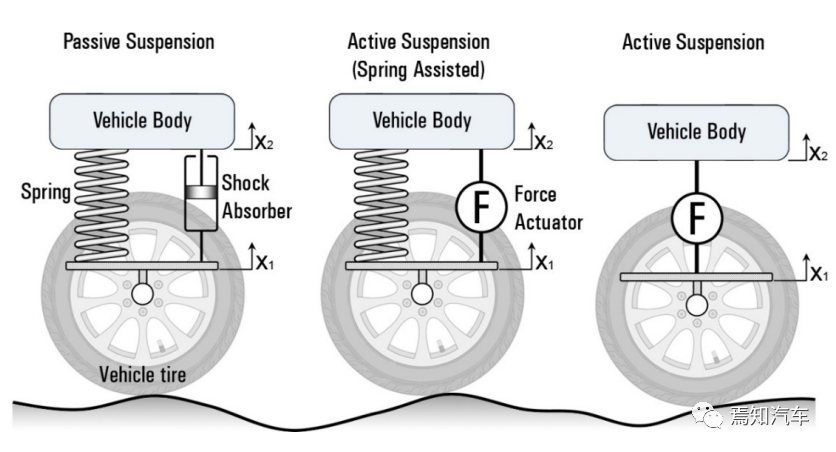
Figure 1 Active suspension frame
The quarter vehicle model is shown in Figure 2 below. In terms of the time it takes to reach driving steady state, both active suspension and passive suspension can do it, but the impact of active suspension is obviously much smaller than that of passive suspension, which will achieve a better balance between ride comfort and vehicle stability. Good compromise.
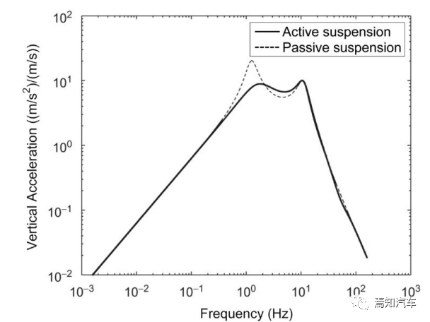
Figure 2 Acceleration frequency response of active and passive suspension
There are currently two recognized forms of active suspension. The first is a fast active suspension or high-bandwidth system (HB), often called fully active. The second is a slow active suspension or low bandwidth system (LB). In active suspension, passive dampers and springs are replaced by force actuators, as shown in Figure 3 below.
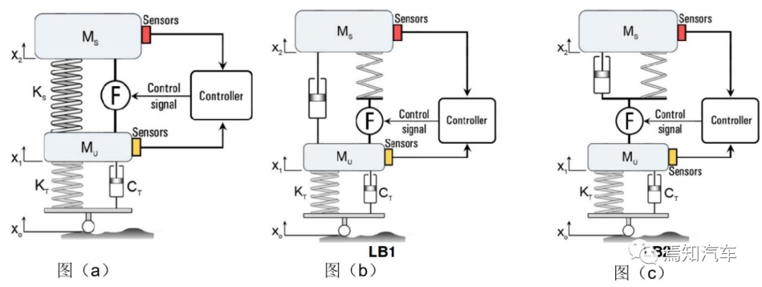
Figure 3 Composition and design principles of different active suspension systems
Fully active suspension systems (high bandwidth), also known as high bandwidth, place the actuator between the sprung and unsprung masses. The primary function of a high-bandwidth system is to control the system over its full bandwidth. Specifically, this means it's designed to enhance suspension response around rattle spatial frequencies (from 10 to 12 Hz) and tire jump frequencies (from 3 to 4 Hz).
In the early days, an active suspension system was also established using an electro-hydraulic servo system (EHS), and a pressure control valve was applied for the first time. The suspension is controlled by a microprocessor and acceleration sensors, and the system emphasizes skyhook dampers, which reduce body vibrations compared to conventional low-frequency suspensions by applying an active damping force to the body relative to its absolute speed. . Hydraulic systems have passive damping characteristics that depend on the excitation frequency of the road input. Enhancements in these characteristics reduce vibrations generated by high-frequency road inputs.
The hardware used in active suspension systems ranges from simple swing dampers, semi-active dampers, low-bandwidth/soft active suspensions to high-bandwidth/rigid active suspensions. Adaptive and semi-active setups are effective means of improving straight-line driving and handling transients, although they don't offer as much improvement in driving as active suspensions.
Slow active suspension system (low bandwidth) is suitable for low bandwidth operation. In this system, the actuator is placed in series with a spring and/or damper. Slow active suspension systems (operating at a low bandwidth of less than 3 Hz) are designed to implement suspension control strategies in the lower frequency range, especially around the rattling spatial frequencies. At higher frequencies, the actuator effectively locks so the wheel hop motion is passively controlled. Low-bandwidth systems can achieve significant reductions in body roll and pitch during maneuvers with lower energy consumption compared to high-bandwidth systems. To provide suspension action beyond the controlled bandwidth, the actuator must be mounted in series with a conventional spring, which in turn reduces the energy requirements of the system.
There are currently two main forms of low-bandwidth systems, as shown in Figure 3(b)(c) above. One form is that the actuator is connected in series with the road spring and has a separate passive damper (LB1), and the other form is The actuator is in the spring and damper series (LB2). In slow-speed active suspensions, passive springs provide the required isolation at high frequencies, while actuators provide vibration control at low frequencies (typically below 3 Hz).
Theoretical studies show that limited-bandwidth active systems perform similarly to fully active systems, but at lower cost and implementation complexity. These studies, based on a quarter car model, show that when components are assumed to be in idealized conditions and the vehicle is operating in straight-line driving conditions, the power requirements will be very modest. Some possible practical implementations of this system have been proposed through the use of hydropneumatic components, such as pneumatic springs with valves to control the air supply and exhaust.
Since the actuators only require a narrow bandwidth of 3-4 Hz, slow active suspension systems are much cheaper than fully active suspension systems which require wideband actuators. But active control still encompasses the normal range of body resonance frequencies in bounce, pitch and roll, as well as the frequency range of interest in terms of response to steering control. Therefore, slow active suspensions are a commercially viable alternative.
Main working mathematical model of active suspension system
1) Mathematical model of electro-hydraulic servo valve
Since the mathematical model of EHSV is described by 27 equations, for simplicity, the typical EHSV model is no longer used in the fully active suspension system model because the calculation and iteration process takes a long time. Therefore, it is important to find the equivalent transfer function of EHSV. To this end, the actuator displacement is calculated to further obtain the transient response of the input current . It is found that the step response of the spool displacement behaves like an over-damped second-order system, which can be described by the following transfer function of the second-order system.
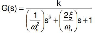
In this transfer function, it is necessary to calculate the coefficients k, ωn and ξ of the corresponding representative transfer function. The gain value (k) is the spool displacement under steady-state conditions divided by the excitation current value of 10 mA. The values of ωn and ξ can be calculated by running a Simulink program.
2) Mathematical model of hydraulic and pneumatic suspension devices
The hydropneumatic suspension device scheme is shown in the figure below. A mathematical model of the system was developed by applying equations describing the dynamic behavior of the suspension units.
The following equation describes this system.

Among them,  is a term that considers the impact of the compressibility of the piston cavity.

Figure 4. Schematic diagram of hydropneumatic suspension Figure 5. Damping system valve of hydropneumatic suspension device
The variable orifice area in the compression and rebound strokes of the damping system as shown in Figure 4 consists of four holes covered by a circular thin plate riveted at its center.
3) Quarter vehicle suspension parameters
The mathematical description of a quarter car model is as follows:

The damping coefficient (CS) of the shock absorber is calculated on the fly based on a proven damper simulation model. F(t) is the excitation acting on the wheel and caused by surface irregularities. If xo is the elevation of the surface profile, ox& represents the vertical speed of the tire at the point of contact with the ground, which is the slope of the road profile multiplied by the forward speed of the vehicle.
Active suspension system design
This article will explain in detail a typical active suspension working model as shown in the figure below, which can help readers quickly understand the working process of active suspension. The model mainly consists of electro-hydraulic servo valve, actuator, air spring, LVDT and controller . Electro-hydraulic drives are widely used in the design of active suspensions, and electro-hydraulic servo systems provide good control from the perspective of accuracy and speed.
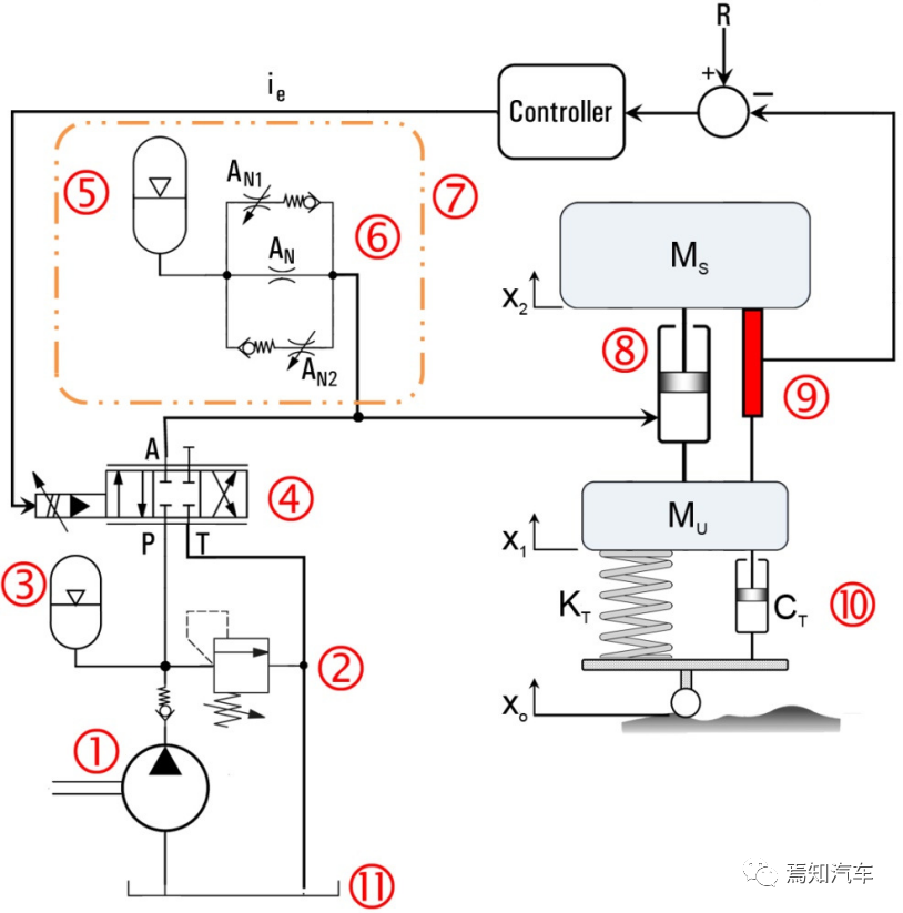
(1) Hydraulic pump (2) Relief valve (3) Accumulator (4) EHSV (5) Accumulator (6) Throttle valve (7) Gas spring (8) Hydraulic actuator (9) LVDT (10 ) Tires (spring + shock absorber) (11) Fuel tank
Figure 6 Active suspension working model
The output control variables are selected to achieve the required dynamic response of the vehicle body, the control structure for measuring the feedback values is constructed, and the measuring device is determined. The designed active suspension system operates in three modes; neutral mode, compression mode and rebound mode.
1) Neutral mode
When the vehicle is driving on a very flat road or when the vehicle is stopped, it means that there is no input displacement from the road surface and there is no relative movement between the body and the wheel assembly. The feedback current from the LVDT and accelerometer is zero, and the error signal (ie) to the servo valve is zero. As shown in the figure (4) above, the valve core of the EHSV is in the neutral position at this time.
Previous article:Magna Launches Industry's First Modular Electronic Disconnect for All-Electric Vehicles
Next article:18 suspension modes? What changes have occurred after the ideal suspension OTA?
- Popular Resources
- Popular amplifiers
- A new chapter in Great Wall Motors R&D: solid-state battery technology leads the future
- Naxin Micro provides full-scenario GaN driver IC solutions
- Interpreting Huawei’s new solid-state battery patent, will it challenge CATL in 2030?
- Are pure electric/plug-in hybrid vehicles going crazy? A Chinese company has launched the world's first -40℃ dischargeable hybrid battery that is not afraid of cold
- How much do you know about intelligent driving domain control: low-end and mid-end models are accelerating their introduction, with integrated driving and parking solutions accounting for the majority
- Foresight Launches Six Advanced Stereo Sensor Suite to Revolutionize Industrial and Automotive 3D Perception
- OPTIMA launches new ORANGETOP QH6 lithium battery to adapt to extreme temperature conditions
- Allegro MicroSystems Introduces Advanced Magnetic and Inductive Position Sensing Solutions
- TDK launches second generation 6-axis IMU for automotive safety applications
- LED chemical incompatibility test to see which chemicals LEDs can be used with
- Application of ARM9 hardware coprocessor on WinCE embedded motherboard
- What are the key points for selecting rotor flowmeter?
- LM317 high power charger circuit
- A brief analysis of Embest's application and development of embedded medical devices
- Single-phase RC protection circuit
- stm32 PVD programmable voltage monitor
- Introduction and measurement of edge trigger and level trigger of 51 single chip microcomputer
- Improved design of Linux system software shell protection technology
- What to do if the ABB robot protection device stops
- What are the functions of the Internet of Vehicles? What are the uses and benefits of the Internet of Vehicles?
- Power Inverter - A critical safety system for electric vehicles
- Analysis of the information security mechanism of AUTOSAR, the automotive embedded software framework
- Brief Analysis of Automotive Ethernet Test Content and Test Methods
- How haptic technology can enhance driving safety
- Let’s talk about the “Three Musketeers” of radar in autonomous driving
- Why software-defined vehicles transform cars from tools into living spaces
- How Lucid is overtaking Tesla with smaller motors
- Wi-Fi 8 specification is on the way: 2.4/5/6GHz triple-band operation
- Wi-Fi 8 specification is on the way: 2.4/5/6GHz triple-band operation
- The express delivery didn’t arrive for 6 days. I took a look and found out that the express delivery also misses home.
- [GD32L233C-START Review] - Transplanting Freertos real-time system
- [Warehouse temperature and humidity automatic control simulation system] 3. RSL10 BLE Mesh networking first experience
- DSP 2812: GPIO encapsulation using C++
- Compound op amp amplification problem
- The DC power supply output voltage is unstable. How to calibrate and test it?
- [National Technology N32G457 Review] 11 N32G45 and STM32 CAN Communication Example
- PCB drawing board suggestions for B628 lithium battery boost circuit chip
- RT Thread IPC Summary
- Offline voice control solution


 AD845KNZ


 京公网安备 11010802033920号