With the popularity of LEDs in car lights , the application requirements of taillights have gradually expanded from simply replacing traditional bulbs to dynamic turn signals and taillight welcome functions. Position lights, brake lights , and turn signals also need to meet functional safety requirements. On the current road, from luxury cars to hot-selling cars and domestic cars, through-type taillights are becoming more and more common, and it seems to have become a trend. Based on these concepts, we share with you the through-type taillight solution based on Infineon PSoC and driver IC. Compared with the previous taillight driver solution, it has fewer wire harnesses, simpler design, and more powerful functions.
The traditional taillight connection method has complex wiring harnesses. If more dynamic effects are required, the MCU+Driver method needs to be configured separately, which has complex software configuration and many wiring harnesses. For this reason, we have proposed a multi-channel LED driver solution with communication, as shown below:

This method realizes modularization and platformization. The light board and control board are separated independently. The control board can match different light board requirements by upgrading the software without changing the hardware:

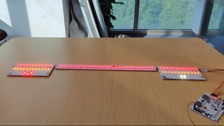
► Scenario application diagram

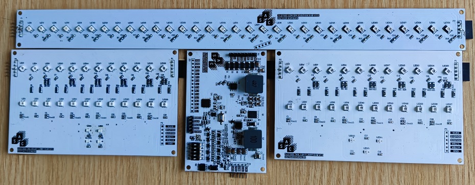
► Product physical image

► Display board photos

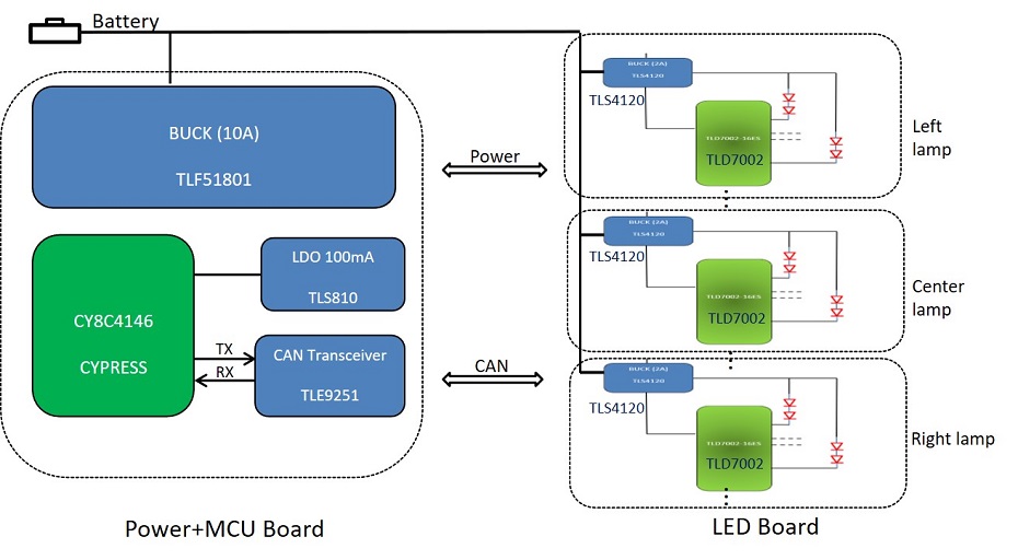
► Solution Block Diagram

► Application Case 01

► Application Case 03

► Core technology advantages
1. A single chip has 16CH output channels, which greatly reduces the number of chips and makes the circuit design simple and reliable;
2. The chip has a built-in transceiver, so there is no need to place a transceiver on the light board;
3. Only 4 wires are needed to connect the light board and the control board, with less wiring harness;
4. Using physical layer CAN communication, the speed is up to 2Mbits/s, which can meet the various dynamic function requirements of tail lights and has strong anti-interference ability;
5. Complete diagnostic protection functions: (VFWD, SLS, Open, Short, NTC, PTC)
6. Meet the ASIL-B functional safety requirements. In case of communication failure, the OTP setting value can be called to control the corresponding channel;
7. The taillight control panel is standardized and platformized. For different models, only the light panel needs to be changed, and the control panel only needs to adjust the software.
► Solution Specifications
> Input voltage: 8-35V > Output voltage: 7.2V
LED Type:
1. Position lights: 56PCS, current: 5-50mA;
2. Brake light : 12pcs per side, current: 5-120mA;
3. Turn signal light: 12pcs per side, current: 5-120mA;
4. Rear fog lamp: 2S2P, current: 5-300mA;
5. Reversing light: 3S1P, current: 5-300mA;
Previous article:Automotive adaptive headlight solution based on Mobileye and S32K144
Next article:Microchip Attiny1616 Touch Sensing Design Solution EVB
- Popular Resources
- Popular amplifiers
- A new chapter in Great Wall Motors R&D: solid-state battery technology leads the future
- Naxin Micro provides full-scenario GaN driver IC solutions
- Interpreting Huawei’s new solid-state battery patent, will it challenge CATL in 2030?
- Are pure electric/plug-in hybrid vehicles going crazy? A Chinese company has launched the world's first -40℃ dischargeable hybrid battery that is not afraid of cold
- How much do you know about intelligent driving domain control: low-end and mid-end models are accelerating their introduction, with integrated driving and parking solutions accounting for the majority
- Foresight Launches Six Advanced Stereo Sensor Suite to Revolutionize Industrial and Automotive 3D Perception
- OPTIMA launches new ORANGETOP QH6 lithium battery to adapt to extreme temperature conditions
- Allegro MicroSystems Introduces Advanced Magnetic and Inductive Position Sensing Solutions
- TDK launches second generation 6-axis IMU for automotive safety applications
- LED chemical incompatibility test to see which chemicals LEDs can be used with
- Application of ARM9 hardware coprocessor on WinCE embedded motherboard
- What are the key points for selecting rotor flowmeter?
- LM317 high power charger circuit
- A brief analysis of Embest's application and development of embedded medical devices
- Single-phase RC protection circuit
- stm32 PVD programmable voltage monitor
- Introduction and measurement of edge trigger and level trigger of 51 single chip microcomputer
- Improved design of Linux system software shell protection technology
- What to do if the ABB robot protection device stops
- ASML predicts that its revenue in 2030 will exceed 457 billion yuan! Gross profit margin 56-60%
- Detailed explanation of intelligent car body perception system
- How to solve the problem that the servo drive is not enabled
- Why does the servo drive not power on?
- What point should I connect to when the servo is turned on?
- How to turn on the internal enable of Panasonic servo drive?
- What is the rigidity setting of Panasonic servo drive?
- How to change the inertia ratio of Panasonic servo drive
- What is the inertia ratio of the servo motor?
- Is it better for the motor to have a large or small moment of inertia?
- 02.USART routines and tests
- How to create and call schematic templates in AD?
- Learning: The most important components of the analog world - signal chain and power supply
- An article to understand the naming of electromagnetic wave bands
- Anlu SparkRoad Development Board Review (3) Official DEMO Test
- [RVB2601 debug record] The function in the c file is not declared in the header file
- Shocked, how can two three-stage tubes make such a posture...
- Analyze several key technologies and application scenarios of the Internet of Things, and understand 5G in seconds
- [Raspberry Pi Pico Review] On-chip temperature detection
- STM32F407 simple vision board (recognition of QR codes, data matrix codes, apriltags, round and square shape detection)

 OPA682N-250


 京公网安备 11010802033920号