By Kyle Lawrence
USB Type-C is a relatively new high-power USB peripheral standard for computers and portable electronic devices. The USB Type-C standard drives a change in the USB power delivery specification. Unlike the long-standing 5 V USB standard, the Type-C standard has a bus voltage of up to 20 V and a current delivery capability of up to 5 A. Connected USB-C devices can recognize each other and negotiate the bus voltage - from the default 5 V USB output to several higher preset voltage levels, to enable faster battery charging and higher power delivery (up to 100 W) when needed.
Simple and compact buck regulators and linear regulators used in battery chargers that only require 5 V, 500 mA to 2 A USB power do not adequately cover the full Type-C USB power range. The increased voltage range of Type-C USB power (5 V to 20 V) requires more than just a step-down conversion from the 9 V to 36 V (or 60 V) car battery or other charging source, but also an adjustable buck-boost converter that can both step up and step down the input-to-output voltage.
Additionally, for high-power automotive USB chargers, the buck-boost converter should support 10 A or higher peak switch current ratings and provide low EMI performance. The ability to set the switching frequency outside the AM radio band and keep the solution size small is a sought-after feature. High-voltage monolithic converters (with on-chip switches) cannot withstand such high peak switch currents without burning up.
The LT8390A is a unique 2 MHz synchronous 4-switch buck-boost controller. At 2 MHz switching frequency, it can provide an output voltage of 5 V to 15 V (up to 45 W at 3 A) to power USB-C devices from a car battery. Such a high controller switching frequency enables a small solution size, high bandwidth, and low EMI outside the AM radio band. Spread spectrum frequency modulation and low EMI current sensing architecture both help LT8390A applications pass the rigors of CISPR 25 Class 5 EMI standards.
High Power Density Conversion: Size (and Power), Efficiency, Heat
The design of a voltage regulator system operating in an automotive or portable electronic device environment is limited by the space requirements of the circuit and the heat generated during operation. These two factors determine the upper limit of the power level that can be achieved when operating within the given design constraints.
Increasing the switching frequency of a design allows for the use of smaller inductors, which are often the largest component in wide input voltage four-switch buck-boost regulator designs. The 2 MHz switching frequency capability of the LT8390A enables the use of much smaller inductors compared to 150 kHz or 400 kHz designs. Figure 1 shows a complete design. In addition to the smaller inductor, this solution uses only ceramic output capacitors, eliminating the need for larger electrolytic capacitors. All components required for the design, including the IC, are contained on a small 1-inch square circuit board, as shown in Figure 1.
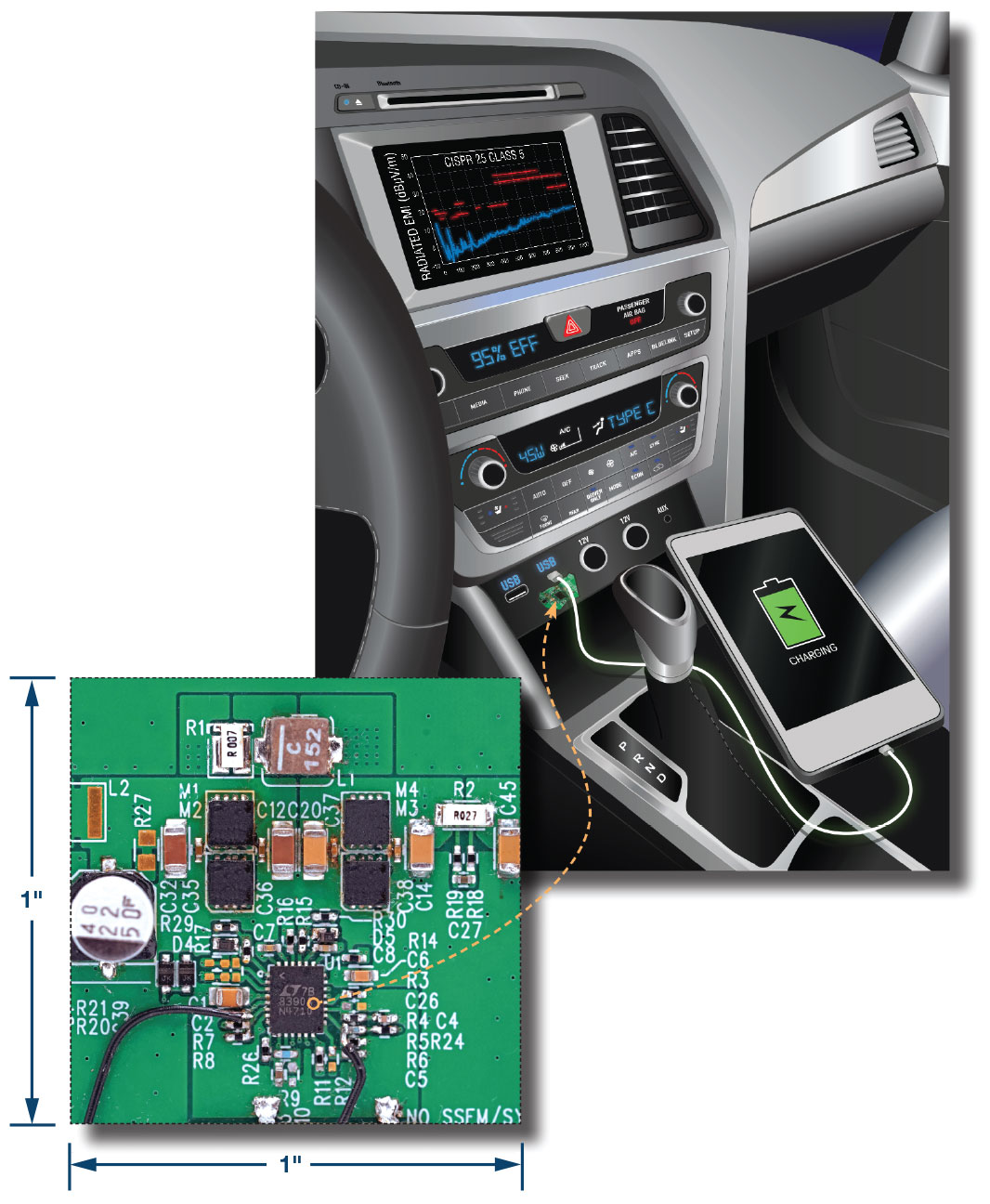
Figure 1. A high-efficiency, low-EMI USB Type-C power solution in a 1-inch square footprint.
Figure 2 shows a 45 W LT8390A solution using AEC-qualified components. The design has a maximum temperature rise of 65°C above ambient, as shown in Figure 3. Despite the small solution size, the LT8390A system achieves a peak efficiency of 94% at 45 W, with less than 10% variation in efficiency over the full input range for each output voltage produced, as shown in the graph in Figure 4.
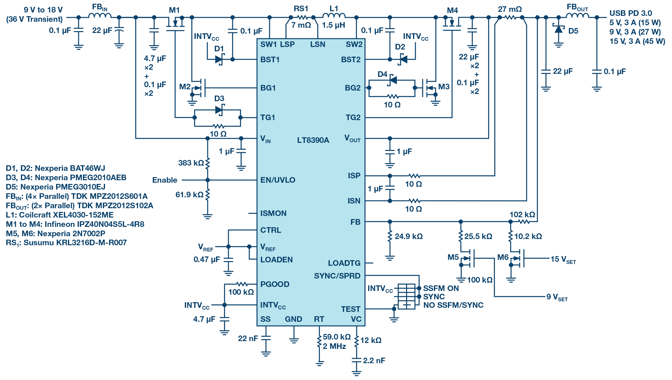
Figure 2. This LT8390A regulator solution uses AEC-qualified MOSFETs, magnetics, and capacitors to provide up to 3 A of current and selectable 5 V, 9 V, or 15 V low EMI outputs.

Figure 3. This small circuit generates a maximum temperature rise of only 65°C above ambient while producing 45 W of output power.

Figure 4. When powered from an automotive SLA battery, the LT8390A regulator system maintains 94% to 84% efficiency for the full output voltage.
Low EMI for automotive applications
LT8390A具有多种独特的降低EMI的特性,可实现高功率转换和低噪声性能,从而简化其在汽车系统中的实施。LT8390A与其他四开关控制器之间的显著差异在于电感电流检测电阻的位置。大多数四开关降压-升压控制器往往使用接地基准电流检测方案来获得开关电流信息,而LT8390A将其电流检测电阻与电感串联。通过将检测电阻与电感串联,便可有效地将电阻从降压和升压热环路中移除,从而缩小环路尺寸并改善EMI性能。
In addition to the architectural advantages of the inductor sense resistor location, the LT8390A also has built-in spread spectrum frequency modulation to further reduce the EMI generated by the controller. In addition, the edge rates of the buck and boost power switches are controlled using only a few discrete components to slow down the turn-on of the MOSFETs, ensuring the right balance between reducing high-frequency EMI and temperature rise of the power switches. With these EMI-reducing features, the only filtering required to meet CISPR 25 standards is provided by small ferrite filters on the input and output, rather than large ferrite cases and bulky LC filters. The solution shown in Figure 1 is designed with AEC-Q100 qualified components.
Seamless transition of output voltage
The output voltage of the LT8390A can be adjusted without shutting down the converter by using a logic level signal to drive a MOSFET, which in turn adjusts a resistor divider at the output to change the set voltage. A USB PD source controller with GPIO pins can be used with the LT8390A system to facilitate the negotiation process between the host and USB-connected devices and set the desired bus voltage.
Figure 5 shows the LT8390A system output transitioning very smoothly from one output voltage to another. When powered from a 12 V input supply, each transition to a higher output voltage takes a maximum of 150 μs to settle, measured from the rising edge of the digital control signal. During the output voltage change, the buck-boost controller undergoes mode transitions between buck, boost, and buck-boost operation, depending on the input to output voltage relationship. These mode transitions are performed in a controlled manner, preventing the output voltage from overshooting or dropping too much.
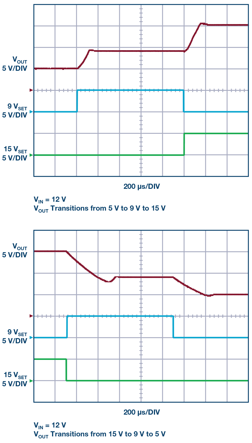
Figure 5. The LT8390A system output smoothly transitions between 5 V, 9 V, and 15 V outputs while continuously delivering power to the output.
Expanded to over 45 W
Increasing output power levels above 45 W requires operation at lower switching frequencies to reduce switching losses, otherwise such power levels may cause thermal stress to the MOSFETs. As an alternative to the LT8390A, the LT8390 operates between 150 kHz and 600 kHz and has the same feature set as the LT8390A, enabling low EMI, high power buck-boost designs. A 400 kHz LT8390 system with larger inductors and output capacitors can easily achieve 100 W of output power from an automotive battery input with acceptable temperature rise. Figure 6 shows the power capabilities of the LT8390A and LT8390 product lines for various battery-powered inputs.
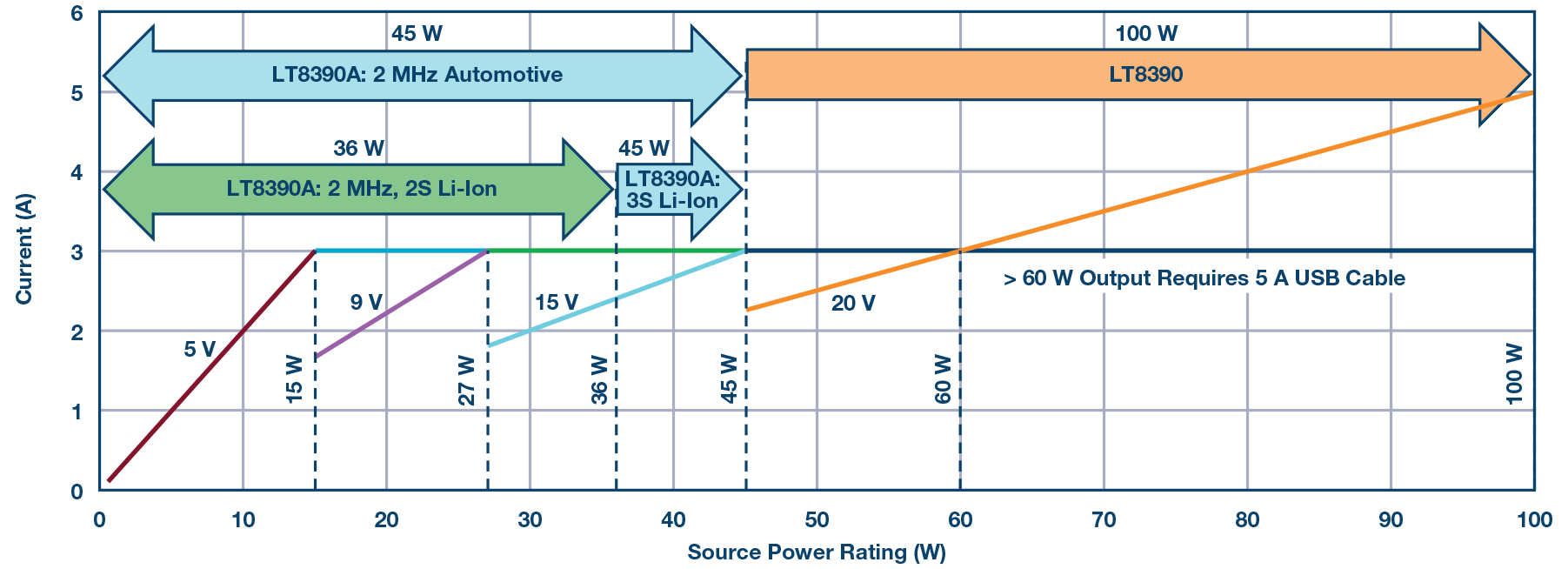
Figure 6. The LT8390A and LT8390 cover various output power levels for USB Power Delivery.
in conclusion
The new USB standard for regulators that power connected devices allows for higher power delivery by increasing the output voltage range and current delivery that the regulator can provide. Portable and automotive battery-powered USB-C charger devices require a wide VIN/VOUT buck-boost regulator to deliver bus voltages above or below the input voltage. The 2 MHz switching frequency allows the LT8390A to deliver up to 45 W of output power in a small solution size. For power levels above 45 W, the LT8390 can be used, although the solution size will increase slightly and the switching frequency will be reduced.
author
Kyle Lawrence is an applications engineer at Analog Devices. He designs and tests a variety of DC-DC converters, including 4-switch buck-boost regulators and LED drivers for low EMI automotive applications. He graduated from UC Santa Cruz in 2014 with a bachelor’s degree in electrical engineering.
Previous article:ON Semiconductor proposes semiconductor solution for mild hybrid vehicle system
Next article:Overcoming electric vehicle range anxiety with wireless
Recommended ReadingLatest update time:2024-11-23 07:56


- Popular Resources
- Popular amplifiers
- 2024 China Automotive Charging and Battery Swapping Ecosystem Conference held in Taiyuan
- State-owned enterprises team up to invest in solid-state battery giant
- The evolution of electronic and electrical architecture is accelerating
- The first! National Automotive Chip Quality Inspection Center established
- BYD releases self-developed automotive chip using 4nm process, with a running score of up to 1.15 million
- GEODNET launches GEO-PULSE, a car GPS navigation device
- Should Chinese car companies develop their own high-computing chips?
- Infineon and Siemens combine embedded automotive software platform with microcontrollers to provide the necessary functions for next-generation SDVs
- Continental launches invisible biometric sensor display to monitor passengers' vital signs
- Intel promotes AI with multi-dimensional efforts in technology, application, and ecology
- ChinaJoy Qualcomm Snapdragon Theme Pavilion takes you to experience the new changes in digital entertainment in the 5G era
- Infineon's latest generation IGBT technology platform enables precise control of speed and position
- Two test methods for LED lighting life
- Don't Let Lightning Induced Surges Scare You
- Application of brushless motor controller ML4425/4426
- Easy identification of LED power supply quality
- World's first integrated photovoltaic solar system completed in Israel
- Sliding window mean filter for avr microcontroller AD conversion
- What does call mean in the detailed explanation of ABB robot programming instructions?
- STMicroelectronics discloses its 2027-2028 financial model and path to achieve its 2030 goals
- 2024 China Automotive Charging and Battery Swapping Ecosystem Conference held in Taiyuan
- State-owned enterprises team up to invest in solid-state battery giant
- The evolution of electronic and electrical architecture is accelerating
- The first! National Automotive Chip Quality Inspection Center established
- BYD releases self-developed automotive chip using 4nm process, with a running score of up to 1.15 million
- GEODNET launches GEO-PULSE, a car GPS navigation device
- Should Chinese car companies develop their own high-computing chips?
- Infineon and Siemens combine embedded automotive software platform with microcontrollers to provide the necessary functions for next-generation SDVs
- Continental launches invisible biometric sensor display to monitor passengers' vital signs
- Silicon Solar Cell Power System
- 【TI recommended course】#TI smart speaker solution full solution: speaker design "listens to you"#
- Corelinks SinA33 development board virtual machine compiles QT and Linux
- Power Technology Application 7 articles
- 1. Material unpacking and data link arrangement
- Code Composer C3x C4x version 4.10 installation package
- Ultrasonic flaw detection system using high-speed and high-resolution signal acquisition card
- Help
- How to use GPIO of TI C55x series DSP
- 【RPi PICO】CircuitPython driver ws2812

 Virtualization Technology Practice Guide - High-efficiency and low-cost solutions for small and medium-sized enterprises (Wang Chunhai)
 usb_host_device_code
 Image acquisition and processing system for panoramic map applications


 京公网安备 11010802033920号