Using multi-channel, multi-speaker systems and advanced audio algorithms, audio systems can simulate real sounds very realistically. These complex audio systems use ASICs or DSPs to decode multi-channel encoded audio and run various post-processing algorithms. More channels mean higher memory and bandwidth requirements, which requires the use of audio data compression techniques to encode and reduce the data to be stored. These techniques can also be used to maintain sound quality.
Along with the development of digital audio, audio standards and protocols have also been developed, whose purpose is to simplify the transmission of audio data between different devices, such as between an audio player and speakers, between a DVD player and an AVR, without having to convert the data into analog signals.
This article will discuss the various standards and protocols related to the audio industry. It will also explore the audio system structure of different platforms and various audio algorithms and amplifiers.
Standards and protocols
S/PDIF standard - This standard defines a serial interface for transmitting digital audio data between various audio devices such as DVD/HD-DVD players, AVRs, and power amplifiers. When audio is transmitted from a DVD player to an audio amplifier via an analog link, noise is introduced that is difficult to filter out. However, if a digital link is used instead of an analog link to transmit audio data, the problem is solved. The biggest advantage of S/PDIF is that data does not have to be converted to analog signals to be transmitted between different devices.
The standard describes a serial, unidirectional, self-clocked interface for interconnecting digital audio devices for consumer and professional applications that use linear PCM encoded audio samples. It is a single-wire, single-signal interface that uses biphase mark encoding for data transmission, with the clock embedded in the data and recovered at the receiving end (see Figure 1). In addition, the data is polarity independent, making it easier to process. S/PDIF evolved from the AES/EBU standard used for professional audio. The two are identical at the protocol level, but the physical connector has changed from XLR to electrical RCA jacks or optical TOSLINK. Essentially, S/PDIF is a consumer version of the AES/EBU format. The S/PDIF interface specification consists mainly of hardware and software. The software generally involves the S/PDIF frame format, while the hardware involves the physical connection medium used to transmit data between devices. Various interfaces for the physical medium include: transistor-transistor logic, coaxial cable (75Ω cable connected with RCA plugs), and TOSLINK (a fiber optic connection).
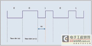
Figure 1 S/PDIF bi-phase mark coded stream
S/PDIF protocol - As mentioned above, it is a single-wire serial interface with the clock embedded in the data. The transmitted data is encoded using bi-phase marks. The clock and frame sync signals are recovered at the receiver along with the bi-phase decoded data stream. Each data bit in the data stream has a time slot. The time slot starts with a transition and ends with a transition. If the transmitted data bit is a "1", a transition is added in the middle of the time slot. Data bits "0" do not require additional transitions, and the shortest interval between transitions is called the unit interval (UI).
S/PDIF frame format - the least significant bit of data is driven first. Each frame has two subframes, each with 32 time slots, for a total of 64 time slots (see Figure 2). The subframe starts with a preamble, followed by 24 bits of data, and ends with 4 bits that carry information such as user data and channel status. The first 4 time slots of the subframe are called the preamble, which is used to indicate the start of the subframe and block. There are three preambles, each of which contains one or two pulses of 3UI duration, thus breaking the bi-phase encoding rule. This means that this pattern cannot exist elsewhere in the data stream. Each subframe starts with a 4-bit preamble. The start of a block is indicated by a preamble "Z" and the start of a subframe channel "A". Preamble "X" indicates the start of a subframe for channel "A" (which is different from the start of a block), and preamble "Y" indicates the start of a subframe for channel "B".
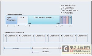
Figure 2 S/PDIF subframe, frame and block formats
I2S bus - In today's audio systems, digital audio data is transmitted between various devices within the system, such as codecs, DSPs, digital IO interfaces, ADCs, DACs, and digital filters. Therefore, in order to enhance flexibility, a standard protocol and communication structure must be available. The I2S bus specification developed specifically for digital audio has been adopted by many IC manufacturers. It is a simple three-wire synchronous protocol that includes the following signals: serial bit clock (SCK), left and right clocks or word selects (WS), and serial data. The WS line indicates the channel being transmitted. When WS is a logic high (HI) level, the right channel is transmitted; when WS is a logic low (LO) level, the left channel is transmitted. The transmitter sends data in binary, with the MSB first. Almost all DSP serial ports use I2S as one of the serial port modes. Audio codecs also support this mode.
Sample Rate Converter (SRC) - This is an important part of the audio system. Sample rate conversion can be implemented in software or supported by on-chip hardware in some processors (see Figure 3). It is mainly used to convert data from one clock domain with a specific sampling rate to another clock domain with the same or different sampling rate.
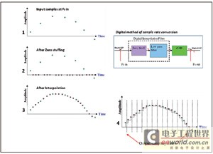
Figure 3. Four different stages of the sampling rate conversion process.
Audio can be encoded at different sample rates, and the codec does the rest. In some cases, the master clock of the codec needs to be changed to support a specific sample rate. Changing the master clock on the fly when switching from audio at one sample rate to audio at a different sample rate is not an easy task, and sometimes even impossible, as it requires changing the hardware on the board. Therefore, the sample rate conversion is usually performed before driving the data to the codec. This way, the sample rate of the codec does not need to be changed and can remain constant. The serial port sends audio data at sample rate 1 to the SRC and codec at the other end, and then reads the audio data from the SRC at sample rate 2.
There are two types of SRC: synchronous SRC and asynchronous SRC. The output device connected to the synchronous SRC is the "slave", and the device connected to the asynchronous SRC is the "master". The "master" refers to the device that drives the SCK and frame synchronization signals.
The SRC converts a discrete-time signal into a continuous-time signal using an interpolation filter and a zero-order hold (ZOH) with a very high output sampling rate. The interpolated values are fed to the ZOH and sampled asynchronously at the output sampling frequency of Fs out.
Audio System
Most handheld audio devices support two channels and can decode MP3, Ogg, WMA media formats. Most of these devices are battery powered. Many mobile phones, some of which are called "music phones", also belong to this category. On the other hand, home theater systems support multi-speaker, multi-channel audio, such as Dolby, DTS and various other audio post-processing algorithms (THX, ART, Neo6, etc.).
Portable Audio Systems - Some handheld audio systems use ASICs, while others use DSPs. Audio content such as MP3, Ogg, and other media files are usually stored in high-density storage devices such as NAND flash, Secure Digital (SD) cards, Multimedia Cards (MMC), and Secure Digital High Capacity (SDHC).
Figure 4 shows the main system interfaces to the ASIC/DSP. SD and MMC also support serial SPI mode, which is commonly available on DSPs and various microcontrollers/microprocessors. Some processors support these standards on-chip. These protocols can also be implemented in software using other resources/interfaces of the processor, such as parallel ports or asynchronous memory interfaces. Of course, software implementation methods increase overhead. For systems running an operating system (OS) or kernel, these interfaces and drivers must be compatible with the OS and should not rely on interrupt services, etc. Unpredictable delays may be introduced in the OS environment, affecting the interface timing specifications, making the interface unreliable and sometimes even non-working. Additional hardware glue logic may be required to ensure OS compatibility.
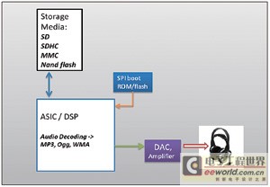
Figure 4 Handheld audio system block diagram
For example, a design example (see Figure 5) implements the SD 2.0 specification on the external memory interface of the processor. The data bus is used not only for data transmission but also for exchanging commands and responses with the SD card. In the 4-bit mode of the SD card, the D0 to D3 signals of the data bus are connected to the data lines (DAT0 to DAT3) of the SD card. D4 of the processor data bus is used for command and response communication with the SD card. Since the command word must be sent serially through the CMD signal, a series of 8-bit words form a frame in the internal memory so that D4 of each word has one bit of the command word in sequence. This data rearrangement is done in software through function calls. Similarly, the software performs data rearrangement on the received status information and the actual data to and from the SD card. The SD card clock signal is obtained from the ARE/ (read enable) and AWE/ (write enable) signals. ARE/ and AWE/ are connected to the input of a buffer with open-collector outputs. AMS3/ (asynchronous memory chip select strobe) is connected to the output enable pin of this buffer. The output of this buffer performs a "wired AND" process, and the resulting signal is provided to the SD card as a clock. The data line is also buffered by a bidirectional buffer.
AMS3/ drives the output enable pin of the buffer. Isolation of the buffer is required so that other asynchronous memory devices can also share the data bus. D5 drives the DIR (direction control) pin of the bidirectional buffer. Pull-up resistors are required on both ends of the buffer. Some other Blackfin products, such as the BF-54x, have on-chip SD support.
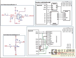
Figure 5 SD design on Blackfin BF-527 processor asynchronous memory interface and parallel peripheral interface
File System – FAT16/32 needs to be implemented to manage audio files and folders on the memory card. These codes are integrated with the audio decoder code. The decoded audio data is then sent to the digital-to-analog converter (DAC) and amplified before being sent to the audio stereo connector. The interface to the DAC is usually a serial I2S interface. DAC configuration is done through a serial peripheral interface (SPI) or an I2C compatible peripheral. Various DAC parameters such as sampling rate, gain/volume control, etc. can be changed at run time through this control interface.
The processor or FPGA bootloads from the SPI boot ROM/flash device. The application is downloaded to its internal memory and executed. The processor uses its internal SRAM to store the encoded audio frames (read from the storage media) and decoded audio data (driven to the DAC) for the IO data buffer.
AVR/Home Theater System - Home theater music systems are typically multi-channel audio systems (see Figure 6). Dolby 5.1 and DTS 5.1 are the mainstream multi-channel audio systems. The DVD player sends the encoded audio data stream through the optical fiber or coaxial cable S/PDIF interface. The system uses an S/PDIF receiver chip to decode the bi-phase mark encoded data and provide a serial frame interface to the processor. The S/PDIF receiver chip usually provides an I2S formatted data stream to the processor. Some processors have an integrated S/PDIF receiver on-chip, eliminating the need for an external receiver chip. The processor runs an automatic detection algorithm to determine the type of data stream, such as Dolby, DTS, or a non-encoded PCM audio stream.
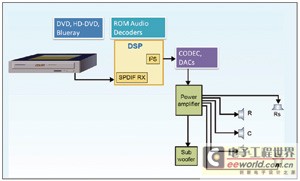
Figure 6 Multi-channel audio system block diagram
This algorithm runs continuously in the background. The auto-detection process is based on the IEC61937 international standard for non-linear PCM coded bitstreams. The main algorithm is called and the various parameters required by the main audio decoder algorithm are correctly passed to the function. The decoded audio data is copied to the allocated output buffer. The serial port is used to drive this decoded audio data to the DAC in I2S format, which then feeds the analog signal to the power amplifier and finally to the speaker.
Audio Algorithms
Audio algorithms can be divided into two categories: main decoder algorithms and post-processing algorithms. Main decoder algorithms include Dolby, DTS 5.1, DTS 6.1, DTS96/24, AAC, etc. Post-decoding or post-processing algorithms include Dolby ProLogic, Dolby ProLogic II, DTS Neo6, Surround EX, Dolby Headphone, Dolby Virtual Speaker, THX, Original Surround Sound, Dynamic EQ, Delay, etc. A high-performance signal processor must be used, and it can perform additional functions such as room equalization.
Audio Amplifier
Amplifiers can be classified into several categories: Class A, Class B, Class AB and Class C. The class of amplifier is basically determined by the operating point or quiescent point of the transistor amplifier. This point is located on the DC load line of the output characteristic of the transistor in the common emitter configuration. The quiescent point represents a specific collector current "IC" relative to a specific base current "IB". The base current "IB" depends on the bias of the transistor and the collector current "IC" is the product of the DC current gain "hfe" and the base current "IB". The quiescent point of the class A amplifier is almost at the midpoint of the effective range of the load line. For any given input signal change, the transistor always operates in the effective range and faithfully amplifies the input signal without causing any interruption or distortion. This type of amplifier is used for amplification of small signals, which can then drive a power amplifier. Since the transistor is always on, it consumes a lot of power and has low power efficiency. This makes the class A amplifier unsuitable for use as a power amplifier. In order to improve efficiency, the transistor must be turned off for a certain period of time, and for this purpose, the quiescent point on the DC load line needs to be lowered, biased towards the cut-off range. This results in other types of amplifiers such as class B, class AB and class C. The Class B amplifier in a push-pull configuration is the preferred power amplifier. It uses two transistors in a push-pull manner, with each transistor conducting for 180°.
However, at crossover, there is a region where neither is conducting, which results in crossover distortion. Class C amplifiers can achieve 80% power efficiency, but because the transistors are conducting for less than 50% of the input signal, the output distortion is high. Using transistors in the active region also requires heat sinks to protect the transistors, which is where Class D amplifier technology excels over other types.
Figure 7 shows a Class D amplifier system. This amplifier is sometimes called a digital amplifier, but it is not. The operating principle is still the same as other types of amplifiers, but the input signal of the Class D amplifier is a PWM (pulse width modulation) signal. Because the digital input switches back and forth between logic high and logic low, the transistor operates in the saturation region or the cutoff region, but never in the active region, so the power consumption is always minimized. This greatly improves power efficiency, but it also causes higher total harmonic distortion (THD).
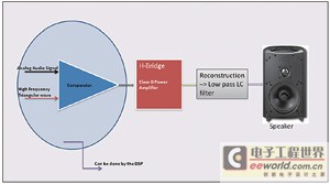
Figure 7 Class D amplifier system block diagram in the analog domain
To demodulate the PWM and reconstruct the original analog waveform, a high-quality low-pass filter consisting of LC (inductor + capacitor) is required. Since most audio systems use DSP, Class D amplifiers are very beneficial for audio system design. The audio signal can be modulated into PWM by the DSP itself and then fed directly to the input of the Class D amplifier without the use of an audio DAC or codec. Therefore, in addition to improving the amplifier power efficiency, it also reduces the system cost by eliminating the codec/DAC. For Class D amplifier design, the low-pass reconstruction filter is the most important factor to ensure good THD performance.
Conclusion
Audio system design has developed rapidly in recent years, especially in the fields of home entertainment and car audio. Various standards, coding technologies and powerful processors have made multi-channel high-definition audio a reality. Audio system designers are still working on various challenges, such as maintaining high power efficiency, achieving lower THD and reproducing high-quality sound.
Previous article:Tips for selecting audio system when modifying car audio system
Next article:Low-power digital receiver demodulation scheme for speech signals
- Popular Resources
- Popular amplifiers
- High signal-to-noise ratio MEMS microphone drives artificial intelligence interaction
- Advantages of using a differential-to-single-ended RF amplifier in a transmit signal chain design
- ON Semiconductor CEO Appears at Munich Electronica Show and Launches Treo Platform
- ON Semiconductor Launches Industry-Leading Analog and Mixed-Signal Platform
- Analog Devices ADAQ7767-1 μModule DAQ Solution for Rapid Development of Precision Data Acquisition Systems Now Available at Mouser
- Domestic high-precision, high-speed ADC chips are on the rise
- Microcontrollers that combine Hi-Fi, intelligence and USB multi-channel features – ushering in a new era of digital audio
- Using capacitive PGA, Naxin Micro launches high-precision multi-channel 24/16-bit Δ-Σ ADC
- Fully Differential Amplifier Provides High Voltage, Low Noise Signals for Precision Data Acquisition Signal Chain
- Innolux's intelligent steer-by-wire solution makes cars smarter and safer
- 8051 MCU - Parity Check
- How to efficiently balance the sensitivity of tactile sensing interfaces
- What should I do if the servo motor shakes? What causes the servo motor to shake quickly?
- 【Brushless Motor】Analysis of three-phase BLDC motor and sharing of two popular development boards
- Midea Industrial Technology's subsidiaries Clou Electronics and Hekang New Energy jointly appeared at the Munich Battery Energy Storage Exhibition and Solar Energy Exhibition
- Guoxin Sichen | Application of ferroelectric memory PB85RS2MC in power battery management, with a capacity of 2M
- Analysis of common faults of frequency converter
- In a head-on competition with Qualcomm, what kind of cockpit products has Intel come up with?
- Dalian Rongke's all-vanadium liquid flow battery energy storage equipment industrialization project has entered the sprint stage before production
- Allegro MicroSystems Introduces Advanced Magnetic and Inductive Position Sensing Solutions at Electronica 2024
- Car key in the left hand, liveness detection radar in the right hand, UWB is imperative for cars!
- After a decade of rapid development, domestic CIS has entered the market
- Aegis Dagger Battery + Thor EM-i Super Hybrid, Geely New Energy has thrown out two "king bombs"
- A brief discussion on functional safety - fault, error, and failure
- In the smart car 2.0 cycle, these core industry chains are facing major opportunities!
- The United States and Japan are developing new batteries. CATL faces challenges? How should China's new energy battery industry respond?
- Murata launches high-precision 6-axis inertial sensor for automobiles
- Ford patents pre-charge alarm to help save costs and respond to emergencies
- New real-time microcontroller system from Texas Instruments enables smarter processing in automotive and industrial applications
- Transistor static operating point
- The History of DSP and Why No One Mentions DSP Anymore
- RISC-V MCU IDE MRS (MounRiver Studio) development: Add standard math library reference
- A brief introduction to the timer A function of the 430 microcontroller
- [Social Recruitment] Capital Securities Recruitment [Semiconductor Researcher]
- [Lazy self-care fish tank control system] PRINTF output in RTT mode under Keil environment
- This week's highlights
- PIC118F
- [MM32 eMiniBoard Review] Part 3: UART Test and Analysis
- Resistance and capacitance thinking map

 5962-8687701Q2A


 京公网安备 11010802033920号