The logistics transport vehicle monitoring terminal designed in this paper obtains the latitude and longitude of the vehicle through GPS satellite positioning, communicates with the monitoring center through the CDMA wireless communication network, and transmits various information of the transport vehicle to the monitoring center in real time, so that the monitoring center can display, query and dispatch the entire transport fleet.
1 Overall system design
The logistics transportation vehicle monitoring system based on GPS and CDMA consists of vehicle monitoring terminal, data transmission network and monitoring center. The data transmission network consists of CDMA network and Internet.
Through the GPS satellite network, the vehicle terminal can accurately locate the logistics vehicles and logistics objects, access the Internet through the CDMA wireless network to link to the monitoring center server, and transmit the logistics vehicle's latitude and longitude, speed, heading, altitude, time and other GPS data information to the monitoring center in real time. The monitoring center can display and query various vehicle information on an electronic map with geographic information processing and query functions, and monitor the vehicle's operating status in real time.
In addition, the monitoring center also has the function of communicating with the on-board terminal, which can dispatch logistics transportation vehicles in real time and handle emergencies in a timely manner. It is suitable for various logistics and transportation fields.
2 Terminal Hardware Design
The hardware structure of the logistics vehicle terminal designed in this paper consists of S3C2440A, JTAG on-chip debugging interface, video interface, audio interface, reset circuit, CDMA wireless communication module, GPS module, power supply circuit, LCD touch screen, keyboard, etc., and external SDRAM, NAND FLASH, and NOR FLASH are used as external memory. Its hardware structure is shown in Figure 1.
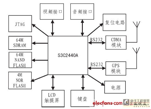
Figure 1 Terminal hardware design hardware structure
2.1 CPU Selection
In order to meet the system's requirements for real-time, large data processing, GPS signal reception, CDMA data transmission, etc., the terminal uses Samsung's S3C2440A 32-bit ARM chip as the CPU. S3C2440A uses the advanced ARM920T core, and integrates 3 UART serial ports, 2 SPI ports, 8 10-bit ADCs, RTC with calendar function, on-chip clock generator with PLL, 130 general I/O ports, 24 external interrupt sources and other rich resources. It is easy to develop and is a very cost-effective chip.
2.2 CDMA module interface design
The terminal uses Huawei EM200 CDMA1X module. The module operates at 800 MHz, with a maximum transmit power of 0.25 W, a receiving sensitivity of less than -106 dBm, an operating voltage of 3.3 to 4.2 V, and integrates a variety of resource interfaces such as UART, UIM card, and antenna. It supports standard AT instruction sets. The extreme operating temperature is -30℃ to +75℃, with a wide operating temperature range, suitable for various logistics and transportation environments.
S3C2440A has three UART serial ports. The EM200 module is connected to S3C2440A through serial port 1. Because both input and output are TTL level, they can be directly connected without level conversion. The pin of EM200 is the data sending end, which is connected to the RXD end of S3C2440A; the pin of EM200 is the data receiving end, which is connected to the TXD end of S3C2440A, thus realizing data transmission and reception between the two. The connection diagram of Huawei EM200 CDMA1X module and S3C2440A is shown in Figure 2.
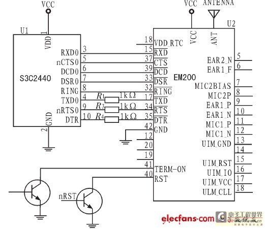
Figure 2 Connection diagram of Huawei EM200 CDMA1X module and S3C2440A
The TXD0, nRTS0, and DTR pins of S3C2440 are connected to the pins of EM200 through three 1 kΩ resistors respectively to prevent damage to the chip caused by excessive current.
2.3 GPS module interface design
The GPS module is the key to the terminal's precise positioning and the core of the terminal design, so this terminal uses Gstar's SIFEIII generation GS-15B module.
GS-15B is a high-performance, low-power intelligent satellite receiving module. It uses the MT3329F satellite positioning receiving chip designed by Taiwan MediaTek Co., Ltd. and is a complete satellite positioning receiver. It also has all-round functions and can meet the strict requirements and industrial-grade needs of professional positioning. It has a built-in GPS antenna and uses MTK's high-sensitivity, low-power chip MT3 329F. It has the ability to quickly locate and track 32 satellites. It is ultra-small in size and has 200,000 built-in computing units on the chip, which greatly improves the ability to search and calculate satellite signals. It supports NMEA-0183 v2.2 version specification output. The receiving sensitivity is -157 dBm, the operating temperature is -40℃~85℃, the TTL level output, the operating voltage is 3.3~5.0 V, the cold start positioning time is only 42 s, and the average positioning accuracy is 10~15 m. It not only meets the terminal's demand for high cost performance, but also meets the terminal's demand for precise positioning.
The interface connection diagram of S3C2440A and GS-15B is shown in Figure 3. The terminal uses the serial port 2 of S3C2440A to connect the GPS module. In order to enhance the driving capability, two 100 kΩ pull-up resistors are added to the TXD1 and PXD1 pins of S3C2440A. The terminal generally only receives GPS information and does not write to the GPS. Therefore, in order to protect the chip, a 100 Ω resistor and a reverse diode of model MCIA148 are added between the RXD1 of S3C2440A and GS-15B, thereby ensuring the stability of the terminal during operation.
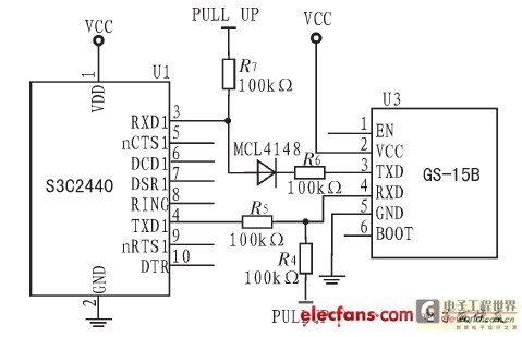
Figure 3 Interface connection diagram of S3C2440A and GS-15B
3 Terminal Software Design
The software part of the terminal is designed based on WinCE 5.0 embedded operating system. WinCE is a multi-tasking, fully preemptive 32-bit embedded operating system that supports WinCE MFC, ATL, WinCE API and some additional programming interfaces and various communication technologies. WinCE embedded operating system has the advantages of good operation interface, high real-time performance, low resource consumption, rich development tools and strong technical support, which fully meets the design requirements of this terminal software.
3.1 Terminal Software Design Process
First, the system is powered on, bootloader is started, WinCE kernel is loaded, and WinCE embedded operating system is started. Then CPU, LCD, GPS, CDMA and other peripheral modules are initialized, and then serial port driver and network protocol are loaded. If the loading is successful, the user application is executed. If the loading fails, it returns and reloads the serial port driver and network protocol. The user application of the terminal includes: CDMA wireless network access program, network data transmission program, GPS serial port receiving program, etc. The terminal software design flow chart is shown in Figure 4.
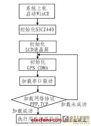
Figure 4 Terminal software design flow chart
3.2 CDMA wireless network access procedures
The terminal controls the CDMA module through AT commands to achieve wireless network access and network data transmission.
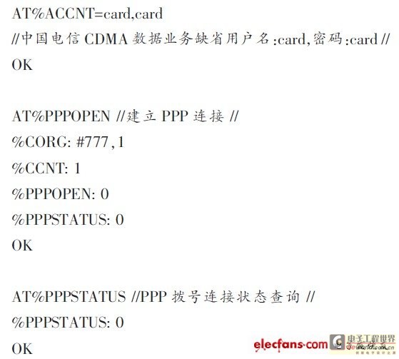
After the system is running, the CDMA module is initialized first, the baud rate is set to 115 200 b/s, and then the dial-up waiting state is entered. The terminal logs into the network through the PPP dial-up connection, the access number is 777, and the user name and password are both card. After confirming that the network login is successful, the GPS serial port receiving program and the network data transmission program are called to send the terminal's GPS positioning information to the monitoring center in a timed manner.
The AT commands and return values for establishing a PPP (point-to-point protocol) connection are as follows:
3.3 CDMA wireless network communication procedures
After the terminal is connected to the Internet through the CDMA network, the wireless network communication program uploads the GPS data parsed by the terminal to the monitoring center through the Internet. This terminal software design uses stream format sockets for network communication, which corresponds to the connection-oriented TCP protocol in the TCP/IP protocol. The network data transmission program is programmed using the client/server mechanism. The terminal (client) process is controlled by the user; while the monitoring center (server) process resides on the host and runs continuously, waiting for the terminal connection request to enter.
The network communication program flow of the monitoring center is as follows: 1) Use the socket() function to create a socket and assign a value to the socket address structure; 2) Use the bind() function to bind the socket to the local IP address and port, and select a static IP address; 3) Use the listen() function to receive a connection request on the socket; 4) Use the accept() function to receive the terminal connection request, generate a new socket and descriptor and connect to the terminal, and use the new socket to send and receive data; 5) Use the fork() function to derive a new child process to communicate with the terminal, and the parent process continues to receive other requests. This can avoid the problem that after a terminal establishes a connection with the monitoring center, the monitoring center can no longer communicate with other terminals.
The TCP program flow of the terminal is as follows: 1) Use socket() to create a local socket and assign a value to the monitoring center socket address structure; 2) Use the connect() function to make the local socket actively send a connection request to the monitoring center socket, and establish a TCP connection through a three-way handshake; 3) If the connection is successfully established, use the send() and recv() functions to communicate with the monitoring center; 4) When the communication is completed, use close() to close the socket.
3.4 Terminal GPS serial port program
The software development tool uses EVC (embedded visual C++), which is the mainstream development tool on Windows CE, encapsulating the underlying network communication, COM interoperability, RAPI, etc. EVC supports a subset of the MFC class library, so that VC programs on the Win32 platform can be easily ported to the WinCE platform.
The terminal GPS serial port program mainly completes two functions: receiving GPS data and parsing GPS data. The GPS module output complies with the NMEA-0183 standard. The program flow is as follows:
1) Use OpenPort() function to open the serial port, which uses the create file function CreatFile() to open serial port 2 to obtain the operation handle m_hComm of serial port 2;
2) If serial port 2 is opened successfully, read the current serial port settings, that is, read the serial port parameter structure DCB variable through GetCommState();
3) Use SetCommState() to set the serial port 2 accordingly: for example, set the baud rate to 4800 b/s, 8 data bits, no parity, 1 stop bit, and no data flow control;
4) Read data bit by bit, determine whether the frame start is $GPRMC, if it is $GPRMC, extract time, longitude, latitude, speed and other information from it and store it in the corresponding structure; determine whether the frame start is $GPGGA, if it is $GPGGA, extract the altitude from the 9th field and store it in the corresponding structure; determine whether the frame start is $GPGSV, if it is $GPGSV, extract the number of valid satellites, valid satellite number and other information from it and store it in the corresponding structure;
5) Use SetWindowText() to display the received GPS data and parsed GPS information on the LCD;
6) Finally, use the ClosePort() function to close serial port 2 when needed. This function uses CloseHandh() to close the handle m_hComm of serial port 2.
4 Operation Results
The running result of the terminal software designed in this paper is shown in Figure 5. The terminal GPS data display includes UTC time, longitude and latitude, ephemeris, direction, altitude, etc. It realizes the function of comprehensive and intuitive display of GPS data, with a friendly human-computer interface style. In Figure 5(a), the GPS serial port can be configured, and the received original NEMA-0183 statement can be displayed. The longitude and latitude in Figure 5(b) were measured at the new campus of Hebei University of Technology in Beichen District, Tianjin, accurate to seconds. The longitude is 117°41'34.4" east longitude and the latitude is 39°37'6.2" north latitude. The test time is June 6, 2010, 16:24:22 p.m.
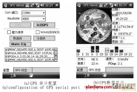
Figure 5 Terminal GPS data display interface
The test shows that the terminal software can run smoothly on the embedded WinCE 5.0 system with good real-time performance and accuracy.
In addition, the terminal transmits GPS positioning data to the monitoring center in real time through the CDMA wireless communication network, and the electronic map of the monitoring center displays the geographical location of the terminal in real time. After testing, the actual location of the terminal is completely consistent with the location on the electronic map, and has good real-time performance, with a data refresh time of less than 3 seconds and a GPS position drift value of less than 20 meters.
5 Conclusion
In view of the rapid development of my country's logistics industry, this paper designs the software and hardware of the logistics vehicle monitoring terminal based on GPS and CDMA. It realizes the remote monitoring and real-time dispatch of logistics vehicles. Compared with the traditional vehicle-mounted terminal, this design uses a 32-bit ARM processor, which has the advantages of faster processing speed, larger storage space, more intuitive interface display, etc. In particular, CDMA wireless communication technology is used in the wireless transmission of GPS data, which is more suitable for the field of vehicle-mounted terminals with long distance, large data volume and very high real-time requirements than traditional GPRS technology.
Previous article:GPS-based time and frequency solutions
Next article:Ultrasonic signal link system partitioning strategy
- Popular Resources
- Popular amplifiers
- High signal-to-noise ratio MEMS microphone drives artificial intelligence interaction
- Advantages of using a differential-to-single-ended RF amplifier in a transmit signal chain design
- ON Semiconductor CEO Appears at Munich Electronica Show and Launches Treo Platform
- ON Semiconductor Launches Industry-Leading Analog and Mixed-Signal Platform
- Analog Devices ADAQ7767-1 μModule DAQ Solution for Rapid Development of Precision Data Acquisition Systems Now Available at Mouser
- Domestic high-precision, high-speed ADC chips are on the rise
- Microcontrollers that combine Hi-Fi, intelligence and USB multi-channel features – ushering in a new era of digital audio
- Using capacitive PGA, Naxin Micro launches high-precision multi-channel 24/16-bit Δ-Σ ADC
- Fully Differential Amplifier Provides High Voltage, Low Noise Signals for Precision Data Acquisition Signal Chain
- Innolux's intelligent steer-by-wire solution makes cars smarter and safer
- 8051 MCU - Parity Check
- How to efficiently balance the sensitivity of tactile sensing interfaces
- What should I do if the servo motor shakes? What causes the servo motor to shake quickly?
- 【Brushless Motor】Analysis of three-phase BLDC motor and sharing of two popular development boards
- Midea Industrial Technology's subsidiaries Clou Electronics and Hekang New Energy jointly appeared at the Munich Battery Energy Storage Exhibition and Solar Energy Exhibition
- Guoxin Sichen | Application of ferroelectric memory PB85RS2MC in power battery management, with a capacity of 2M
- Analysis of common faults of frequency converter
- In a head-on competition with Qualcomm, what kind of cockpit products has Intel come up with?
- Dalian Rongke's all-vanadium liquid flow battery energy storage equipment industrialization project has entered the sprint stage before production
- Allegro MicroSystems Introduces Advanced Magnetic and Inductive Position Sensing Solutions at Electronica 2024
- Car key in the left hand, liveness detection radar in the right hand, UWB is imperative for cars!
- After a decade of rapid development, domestic CIS has entered the market
- Aegis Dagger Battery + Thor EM-i Super Hybrid, Geely New Energy has thrown out two "king bombs"
- A brief discussion on functional safety - fault, error, and failure
- In the smart car 2.0 cycle, these core industry chains are facing major opportunities!
- The United States and Japan are developing new batteries. CATL faces challenges? How should China's new energy battery industry respond?
- Murata launches high-precision 6-axis inertial sensor for automobiles
- Ford patents pre-charge alarm to help save costs and respond to emergencies
- New real-time microcontroller system from Texas Instruments enables smarter processing in automotive and industrial applications
- High-performance machine learning makes edge computing more powerful
- 100 Rules of Thumb for Signal Integrity----
- How to Design Automotive Transient and Overcurrent Protection Filters
- [ATmega4809 Curiosity Nano Review] Using MPLAB Xpress
- 【e-Network Alliance e-Select】Quickly place orders and post them
- Shanghai ACM32F070 development board evaluation 3, USART
- PCB Capacitor and Resistor Failure Analysis
- Application Note: LPS33HW Digital Pressure Sensor - System Integration Guide
- Python3 Basic Tutorial (Complete Version)
- TI reference designs bring more imagination to next-generation home appliances

 AD8622ARMZ-REEL


 京公网安备 11010802033920号