Introduction
In the industrial control process, some parameters often need to be measured, and the output signals of general sensors are weak and are not suitable for long-distance transmission. In order to reduce interference, a twisted pair transmitter with a current output of 4mA~20mA is usually used. Due to the limitation of circuit complexity, the signal simulation processing transmitter has unsatisfactory nonlinear compensation effect and it is difficult to achieve temperature compensation within the full temperature range, so it cannot meet higher accuracy requirements. With the increasing popularity of low-power high-precision microcontrollers, ΣΔA/D and ΣΔD/A converters, technical approaches are provided for the design of high-precision smart transmitters. This article introduces the hardware structure and working principle of a high-precision intelligent transmitter using a powerful low-power microcontroller recently launched by Texas Instruments.
System hardware composition and working process

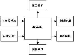
Figure 1 Smart transmitter hardware composition diagram
The hardware system structure of the smart transmitter is shown in Figure 1. The system consists of pressure sensor, temperature measurement chip, low-power microcontroller MSC1211, liquid crystal display, programming interface, power management and current output. The LCD display uses a parallel interface, and the programming interface uses a serial port. Since the two-wire transmitter produced requires the output current to be 4~20mA when the loop is powered, and considering other influences, the current of the entire system is required to be around 3.5mA, so that it is easier to adjust 4mA at zero pressure. Therefore, power consumption should be considered when selecting devices. The microcontroller and LCD display with on-chip D/A and A/D used in this system have power-saving functions, and the temperature chip is a single-wire system with low power consumption. When designing the software, let the communication part and sampling part work in a time-sharing manner to ensure that the entire system is around 3.5mA. MSC1211 consumes less than 4mW at an operating voltage of 2.7~5.25V, and the operating current of the LCD is less than 50μA; in addition, MSC1211 can provide an accurate 2.5V or 1.25V reference voltage as the reference voltage for A/D and D/A converters.
The working process of the system: The signal from the pressure sensor enters the A/D converter, which has a programmable gain amplifier inside, which can automatically set the gain amplification factor according to the range of the input signal. The A/D converter digitizes the analog signal and digitizes it. After digital filtering, the CPU reads the zero point and linearity correction coefficient from the FALSH memory according to the temperature signal read from the temperature chip DS18B20, performs temperature compensation and nonlinear compensation, and then performs range conversion according to the range range and sends it to the to the D/A converter, thereby outputting the corresponding current value, and at the same time displaying the pressure on the LCD in the corresponding unit.
MSC1211 A/D and D/A Converters
The MSC1211's on-chip A/D converter is a highly integrated, eight-channel differential and single-channel 24-bit Σ-Δ A/D converter. It includes instrumentation amplifiers, programmable gain amplifiers, multiplexers, digital filtering, data processing and signal calibration circuits. The chip can provide its own high-precision standard voltage with an accuracy of 0.2% and a drift of 5ppm/°C, thus saving space and device costs. It can also output this voltage standard or an external voltage standard. Thus, the 0~100mV micro-signal output by the external sensor can be collected.
A/D converter settings:
When using the MSC1211's on-chip A/D for sampling, the registers that need to be set are the multi-way switch register (ADMUX), the analog-to-digital conversion control register (ADCON0~ADCON3), the summation and shift register ( Summation/Shift Control) and ADC offset setting register (OCL~OCH). ADCON0 determines the gain of the internal amplifier and the reference voltage for AD conversion, etc. ADCON1 determines the polarity, digital filtering method and calculation mode control bit of the AD conversion result, and ADCON2~3 is used to design the rate of AD conversion output data. The summation and shift register are used to design the number of samples that need to be sampled for one output. For example, it can be set to perform 8 AD conversions and then average the data to output. The ADC offset setting register is used to store the zero offset for easy correction.
Example of A/D conversion program:
The following is the AD sampling program we use in the smart transmitter. It has been compiled in the KEILC51V7.05 environment and downloaded from the serial port of the computer to the circuit board of the smart transmitter. It can correctly sample and Display on the LCD and obtain the corresponding current value through the DA converter.
#include
#define
//Set the AD conversion rate 10 times per second
ADCON3=(DECIMATION>>8) & 0x07;
ADCON1 = 0x01; //Set the filtering method
ADMUX=0X10;
PDCON&=0x0f7; //Open the AD converter
while(1)
{
display ((ADRESH); //Call the display function to display the conversion result
display((ADRESM);
display((ADRESL);
}
}
D/A converter settings:
Compared to A/D conversion, the D/A converter settings are very simple. It needs to configure 4 DA conversion registers (DAC0~DAC3) and DAC load control register. The DA conversion register controls the corresponding voltage output mode and reference voltage. The load control register is used to control the way of loading DA data.
Software design
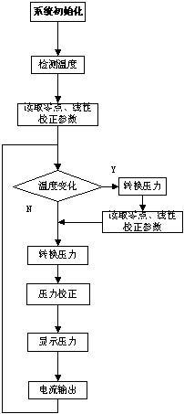
The software part of the intelligent transmitter includes the following modules: (1) Initializing MSC1211 includes initializing the microcontroller, liquid crystal display, A/D converter and D/A converter. (2) The calibration of the A/D converter includes gain and zero drift correction of each channel. (3) Collection of on-site pressure and temperature data (4) Zero point calibration of pressure sensor, temperature drift compensation and nonlinear compensation (5) Range conversion, D/A data output (6) Real-time pressure display. The software flow chart is shown in Figure 2.

Figure 2 Software flow chart
Table 1: Pressure test results at different temperatures (pressure unit kPa, temperature unit °C)
| standard value | 20 | 40 | 60 | 80 |
| temperature | ||||
| 20 | 19.988 | 39.990 | 60.012 | 79.985 |
| 40 | 20.003 | 40.005 | 59.988 | 80.005 |
| 60 | 20.010 | 39.985 | 60.010 | 79.990 |
The experimental results
are based on the use of the SensymICT19C series piezoresistive pressure sensor. Its main technical indicators are: range 100kPa, sensitivity 2mV/V, zero point ±2mV, linearity ±0.2%, and operating temperature -40~125°c . The input signal range of the A/D converter is set to ±100mV. After temperature drift compensation and nonlinear correction, the test results are as shown in Table 1. After calculation, the accuracy is within three thousandths, which satisfies Meet the requirements for manufacturing high-precision transmitters.
Conclusion
The smart transmitter designed using the solution proposed in this article has the characteristics of high precision, online programming, small size, and ease of use. It can be applied in many fields where weak parameters need to be detected.
References:
1 MSC1211 Datasheet, Texas Instruments.
2 DEM_MSC1211User's Guide, Texas Instruments.
3. Jiang Jianxin, Lu Aizhi Design and Measurement Technology of Intelligent Transmitter Control Board, 1998, 18 (4): 49~51
Previous article:Video output stage circuit to reduce power consumption of high-performance portable electronics
Next article:Application of MSC1211 in the development of high-precision intelligent transmitters
Recommended ReadingLatest update time:2024-11-16 17:53

- High signal-to-noise ratio MEMS microphone drives artificial intelligence interaction
- Advantages of using a differential-to-single-ended RF amplifier in a transmit signal chain design
- ON Semiconductor CEO Appears at Munich Electronica Show and Launches Treo Platform
- ON Semiconductor Launches Industry-Leading Analog and Mixed-Signal Platform
- Analog Devices ADAQ7767-1 μModule DAQ Solution for Rapid Development of Precision Data Acquisition Systems Now Available at Mouser
- Domestic high-precision, high-speed ADC chips are on the rise
- Microcontrollers that combine Hi-Fi, intelligence and USB multi-channel features – ushering in a new era of digital audio
- Using capacitive PGA, Naxin Micro launches high-precision multi-channel 24/16-bit Δ-Σ ADC
- Fully Differential Amplifier Provides High Voltage, Low Noise Signals for Precision Data Acquisition Signal Chain
- Innolux's intelligent steer-by-wire solution makes cars smarter and safer
- 8051 MCU - Parity Check
- How to efficiently balance the sensitivity of tactile sensing interfaces
- What should I do if the servo motor shakes? What causes the servo motor to shake quickly?
- 【Brushless Motor】Analysis of three-phase BLDC motor and sharing of two popular development boards
- Midea Industrial Technology's subsidiaries Clou Electronics and Hekang New Energy jointly appeared at the Munich Battery Energy Storage Exhibition and Solar Energy Exhibition
- Guoxin Sichen | Application of ferroelectric memory PB85RS2MC in power battery management, with a capacity of 2M
- Analysis of common faults of frequency converter
- In a head-on competition with Qualcomm, what kind of cockpit products has Intel come up with?
- Dalian Rongke's all-vanadium liquid flow battery energy storage equipment industrialization project has entered the sprint stage before production
- Allegro MicroSystems Introduces Advanced Magnetic and Inductive Position Sensing Solutions at Electronica 2024
- Car key in the left hand, liveness detection radar in the right hand, UWB is imperative for cars!
- After a decade of rapid development, domestic CIS has entered the market
- Aegis Dagger Battery + Thor EM-i Super Hybrid, Geely New Energy has thrown out two "king bombs"
- A brief discussion on functional safety - fault, error, and failure
- In the smart car 2.0 cycle, these core industry chains are facing major opportunities!
- The United States and Japan are developing new batteries. CATL faces challenges? How should China's new energy battery industry respond?
- Murata launches high-precision 6-axis inertial sensor for automobiles
- Ford patents pre-charge alarm to help save costs and respond to emergencies
- New real-time microcontroller system from Texas Instruments enables smarter processing in automotive and industrial applications
- Apply for free | STM32F7508-DK Discovery Kit and have a chance to win a prize of 10,000 yuan!
- RK3399 delete the boot lock screen interface
- Let's talk about DSP audio processing
- How to download STBLESensor?
- 【LSM6DSOX's MLC machine learning understanding】--Introduction to machine learning
- CPU card programming process
- Blind guess: How does the ESP32 “Piranha Plant” design achieve the opening and closing of its petals?
- The calculation problem of frequency count value
- 13.56MHz ultra-low power contactless card reader chip Si522_Provide technical support
- EEWORLD University Hall----Sharing the application solution of sensorless FOC portable refrigerator based on Lingdong MM32SPIN series MCU

 CVPR 2023 Paper Summary: Photogrammetry and Remote Sensing
 New Concept Analog Circuit 1-Transistor [Text Version] (Yang Jianguo)


 京公网安备 11010802033920号