Introduction
In industrial sites, when signals are transmitted between electrical equipment and instruments at a long distance, interference often occurs, causing system instability or even erroneous operation. In addition to the influence of internal and external interference in the system, another very important reason is the grounding treatment of various instruments and equipment. In general, the equipment casing needs to be connected to the ground, and the circuit system must also have a common reference ground. However, due to the potential difference between the reference points of each instrument and equipment, a ground loop is formed. Since the ground wire loop current will bring common-mode and differential-mode noise and interference, the system often cannot work properly.
An ideal solution is to electrically isolate the equipment, so that the originally interconnected ground wire network becomes an independent unit, and the interference between them will be greatly reduced.
In industrial automation control systems, instrumentation, and sensor applications, 4~20mA current is widely used to transmit control and detection signals. Because the 4~20mA current loop has strong anti-interference ability and simple circuits, it can be used to transmit analog signals of tens or even hundreds of meters. In general, if the transmission distance exceeds 10 meters, the current signal needs to be isolated.

IDC3516 current loop isolation interface chip
IDC3516 is a monolithic two-wire isolation interface chip. The chip contains a current signal modulation circuit, a magnetoelectric coupling isolation conversion circuit and a demodulation circuit. Through magnetic circuit coupling, energy is transferred from the input line to the output side, and no direct electrical connection is required. The typical value of IDC3516 nonlinearity is 0.2%, and the temperature drift coefficient is 100ppm. It is suitable for most industrial control and measurement occasions. The input signal of the chip is 4~20mA, and the output signal is 4~20mA after isolation. The input equivalent resistance of the chip is small, the linearity is high, and it has a wide input/output creepage distance. Figure 1 is the internal schematic diagram of IDC3516. Among them, pin 24 is the input current signal inflow end, pin 23 is the input current signal outflow end, pins 22 and 21 are the zero point and full scale adjustment potentiometer access ends, and pins 11 and 10 are the output current outflow and inflow ends.

IDC3516 application circuit
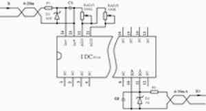
Since all functions are integrated inside the chip, IDC3516 is very convenient to use. In practical applications, only a few protection and adjustment components are needed. Figure 2 shows the typical wiring schematic of the IDC3516 series chip. The potentiometer RADJ1 connected between pins 22 and 23 is used to adjust the ratio of input current Ii to output current Io. The variable resistor RADJ2 connected between pins 21 and 22 is the bias adjustment resistor of the output current Io. D1 and D2 are limiter voltage regulators used for line surge voltage and lightning strong interference protection. F1 and F2 are self-recovery fuses used for overcurrent protection in the line. C1 and C2 are filter capacitors. Generally, 1mF ceramic capacitors can be selected to filter out high-frequency differential mode interference and reduce the pulsation components of input and output signals.

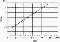
Since the chip consumes some energy in signal transmission, the output signal power of the chip is always less than the input power, which is reflected in the voltage drop at the input end. Figure 3 is the input characteristic curve of the chip. The load on the output side is 250Ω. It can be seen that in this case, the signal source needs to have sufficient driving capability (>14V).
Conclusion
The 4~20mA current loop isolation interface chip IDC3516 has a simple wiring circuit and is easy to use. It can be widely used in industrial sites with long-line transmission such as automatic control, instruments and meters, and sensors.
Previous article:Improved method for parallel data interface in optoelectronic devices
Next article:Implementation of analog programmable design based on switched capacitor
Recommended ReadingLatest update time:2024-11-16 17:32

- Popular Resources
- Popular amplifiers
- High signal-to-noise ratio MEMS microphone drives artificial intelligence interaction
- Advantages of using a differential-to-single-ended RF amplifier in a transmit signal chain design
- ON Semiconductor CEO Appears at Munich Electronica Show and Launches Treo Platform
- ON Semiconductor Launches Industry-Leading Analog and Mixed-Signal Platform
- Analog Devices ADAQ7767-1 μModule DAQ Solution for Rapid Development of Precision Data Acquisition Systems Now Available at Mouser
- Domestic high-precision, high-speed ADC chips are on the rise
- Microcontrollers that combine Hi-Fi, intelligence and USB multi-channel features – ushering in a new era of digital audio
- Using capacitive PGA, Naxin Micro launches high-precision multi-channel 24/16-bit Δ-Σ ADC
- Fully Differential Amplifier Provides High Voltage, Low Noise Signals for Precision Data Acquisition Signal Chain
- Innolux's intelligent steer-by-wire solution makes cars smarter and safer
- 8051 MCU - Parity Check
- How to efficiently balance the sensitivity of tactile sensing interfaces
- What should I do if the servo motor shakes? What causes the servo motor to shake quickly?
- 【Brushless Motor】Analysis of three-phase BLDC motor and sharing of two popular development boards
- Midea Industrial Technology's subsidiaries Clou Electronics and Hekang New Energy jointly appeared at the Munich Battery Energy Storage Exhibition and Solar Energy Exhibition
- Guoxin Sichen | Application of ferroelectric memory PB85RS2MC in power battery management, with a capacity of 2M
- Analysis of common faults of frequency converter
- In a head-on competition with Qualcomm, what kind of cockpit products has Intel come up with?
- Dalian Rongke's all-vanadium liquid flow battery energy storage equipment industrialization project has entered the sprint stage before production
- Allegro MicroSystems Introduces Advanced Magnetic and Inductive Position Sensing Solutions at Electronica 2024
- Car key in the left hand, liveness detection radar in the right hand, UWB is imperative for cars!
- After a decade of rapid development, domestic CIS has entered the market
- Aegis Dagger Battery + Thor EM-i Super Hybrid, Geely New Energy has thrown out two "king bombs"
- A brief discussion on functional safety - fault, error, and failure
- In the smart car 2.0 cycle, these core industry chains are facing major opportunities!
- The United States and Japan are developing new batteries. CATL faces challenges? How should China's new energy battery industry respond?
- Murata launches high-precision 6-axis inertial sensor for automobiles
- Ford patents pre-charge alarm to help save costs and respond to emergencies
- New real-time microcontroller system from Texas Instruments enables smarter processing in automotive and industrial applications
- CircuitPython upgrade micropython kernel
- Common data storage for python crawlers
- Embedded processor architecture and core
- MSP430F5529 ADC sampling example
- 5 days left to register | Full schedule of the annual AIoT Developer Conference! 19 technical lectures full of practical information!
- STEVAL-IDB010V1 BlueNRG-LP evaluation board data
- Revealing the secret! How can 100 MHz power decoupling hold Gbps high-speed signals?
- Please tell me how to protect the gas meter using Hall device from strong magnetism, and whether it has one or two Hall devices.
- I don't know how many days I have been learning HFSS
- [STM32F769Discovery development board trial] USB-HS HID simple transmission and reception evaluation

 Multi-port and shared memory architecture for high-performance ADAS SoCs
 CVPR 2023 Paper Summary: Transparency, Fairness, Accountability, Privacy, Ethics in Vision


 京公网安备 11010802033920号