With the continuous development of broadband wireless communication systems, the demand for high-sensitivity, large dynamic range, and high-efficiency broadband amplifiers is also increasing. In a sense, the performance of broadband amplifiers directly determines the performance of microwave systems. However, in the design process of broadband amplifiers, the output reflection coefficient S22 of the gallium arsenide heterojunction bipolar transistor (HBT) in the co-transmission configuration working mode will show the Kink effect at a certain frequency. Therefore, when using HBT to implement broadband amplifiers, it will bring difficulties to the broadband output matching design with the working frequency band crossing the Kink point. At present, the effective methods to expand the bandwidth include inverse proportional cascade, parallel peak, capacitor peak, distributed amplifier and fT multiplier technology. However, these methods will increase the complexity of the circuit to varying degrees.
This paper uses a composite transistor structure that improves the HBT Kink effect to extend the bandwidth of the amplifier and simplify the design of broadband output matching.
Since Shey-Shi Lu, Yo-Sheng Lin and others proposed the Kink effect of HBT, the small signal theoretical analysis of this phenomenon has become more mature. The literature proposed a new HBT composite transistor structure based on negative feedback technology, which can effectively eliminate the small signal Kink effect of HBT. However, large signal research on this phenomenon is relatively rare.
This paper first studies the large signal Kink effect of HBT based on AWR software, and then uses a new HBT composite tube and a common HBT tube (hereinafter referred to as composite tube and common tube respectively) to complete the design of two broadband power amplifiers. Through software simulation, the results show that the new HBT composite transistor can not only effectively eliminate the large signal Kink effect of HBT, but also significantly expand the bandwidth of the amplifier, improve the gain-bandwidth product, and simplify the impedance matching design of the output end.
1 Large signal characteristics of the new HBT composite transistor
1.1 Small signal Kink effect of HBT
As the frequency increases, the influence of the transistor's own parasitic capacitance Cce, Cbe, Cbc, etc. on the device performance increases significantly, causing the output reflection coefficient S22 in the HBT co-transmission configuration working mode to have an inflection point at a certain frequency. This phenomenon is called the Kink effect, as shown in Figure 1. In addition, as the device size increases, the Kink effect tends to increase.
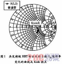
It can be seen that the output impedance of HBT is equivalent to a series RC circuit at low frequency, and is equivalent to a parallel RC circuit at high frequency. The inflection point shown in Figure 1 appears during the transition between the two equivalent circuits, namely the Kink effect. In order to effectively eliminate the Kink effect of HBT, the literature proposes a new HBT compound transistor structure based on negative feedback technology. This paper adds a resistor R2 to the structure to adjust the feedback strength and phase. Its topology is shown in Figure 2.
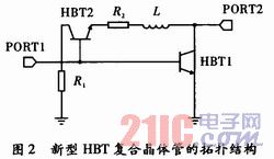
In Figure 2, the common emitter connected HBT1 works in the amplification state as a conventional amplifier, and HBT2 works in the reverse state as the negative feedback branch of HBT1. The emitter of HBT2 is connected to the output end of the circuit through a small inductor L and a small resistor R2. Since the inductor balances the influence of the parasitic capacitance on the output impedance, the small signal output impedance of the HBT in the common emission configuration working mode is close to a simple RC series circuit in the entire working frequency band, and the resistance value R is a constant, which can effectively eliminate the small signal Kink effect of the HBT.
1.2 Large signal Kink effect and its elimination
When the power amplifier works in the large signal state, the working state and equivalent circuit model of the HBT amplifier tube are different from those in the small signal state. In order to deeply study the large signal Kink effect of HBT, two single-stage amplifier circuits are designed using a new HBT composite tube and an ordinary HBT tube, as shown in Figure 3. At the same time, the simulation curve of its large signal S22 changing with frequency is shown in Figure 4.
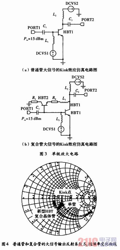
The simulation results in Figure 4 show that S22 of the HBT also has the Kink effect under large signal input conditions. However, the use of a composite tube structure can make the output impedance of the HBT under large signal conditions a constant over a wide frequency range, and the Kink effect of S22 is effectively eliminated.
The load characteristics of the power amplifier output will directly affect the complexity of the output matching circuit. In order to obtain the optimal power output load impedance, a conventional load-pull test is performed in the 4-12 GHz frequency band to obtain the optimal output power and power gain. The output load impedance value required by the design is obtained by Load-Pull, and the result is shown in Figure 5.
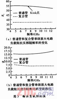
As shown in Figure 5, the Load-Pull results show that the real and imaginary parts of the optimal load impedance of the ordinary tube circuit change with frequency throughout the frequency band, while the output impedance of the composite tube circuit does not change much with frequency. Therefore, using this structure as the active amplifier device of the broadband power amplifier can simplify the power matching circuit design at its output end and obtain better power output characteristics.
2 Amplifier Design
Based on the above small signal and large signal characteristic analysis, two broadband power amplifiers are designed using ordinary tubes and composite tubes respectively. The matching circuit adopts the basic LC matching structure. The input matching satisfies the high-pass characteristic, and the output matching satisfies the low-pass characteristic, as shown in Figure 6.
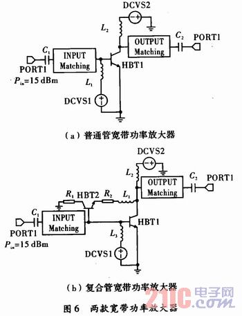
In the microwave frequency band, the reverse transmission scattering parameter S12 of GaAs HBT is very small. Therefore, the one-way model can be approximated as one-way after slight modification, so that the input and output matching networks of this device can be designed separately to solve the matching problems of the input and output ends of the broadband power amplifier respectively. Since the gain of the active device decreases by 6 dB octaves as the frequency increases, the input matching network needs to provide a gain compensation to ensure the flat gain characteristics of the amplifier. In order to make the gain of the amplifier flatter, CAD technology is used to optimize the preliminary design results of the circuit, and finally a more satisfactory single-stage power amplifier is obtained.
The large signal parameters of the composite tube broadband amplifier at the Kink frequency point are shown in Figure 7(a). The small signal parameter simulation curve in the 5-12 GHz band and the comparison of the bandwidth characteristics of the power gain of the two amplifiers are shown in Figure 7(b).
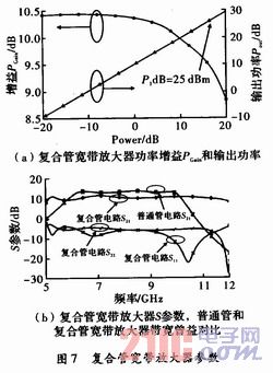
As can be seen from Figure 7, in the operating frequency range of 6 to 10 GHz, the power gain of the ordinary tube amplifier is PGain = 12 dB, and the gain-bandwidth product is 16 GHz. The power gain of the composite tube structure amplifier is PGain = 11 dB, the bandwidth is extended to 5 to 12 GHz, and the gain-bandwidth product reaches 25 GHz, which is significantly higher than the former. The above results well illustrate that the use of the new HBT composite tube structure can effectively eliminate the large signal Kink effect of HBT, thereby expanding the amplifier bandwidth. At the same time, the designed composite tube structure broadband power amplifier has a high power output in the entire frequency range and has practical application value.
3 Conclusion
A 5-12 GHz broadband power amplifier was designed using a new HBT composite transistor structure, and CAD optimization was performed using AWR software to achieve higher performance indicators for the broadband power amplifier. On the other hand, a broadband power amplifier circuit was designed using an ordinary tube HBT as a comparison. The results show that the use of this new HBT composite transistor structure as an active device can effectively eliminate the large signal Kink effect of Ga-As HBT, and the use of it to design a broadband power amplifier can effectively improve the gain-bandwidth product of the amplifier. At the same time, compared with other technologies, the amplifier has a simple structure and good practical application value.
Previous article:Tube amplifier single tube output and push-pull output
Next article:Testing Sample and Hold Amplifiers with Circuits
- High signal-to-noise ratio MEMS microphone drives artificial intelligence interaction
- Advantages of using a differential-to-single-ended RF amplifier in a transmit signal chain design
- ON Semiconductor CEO Appears at Munich Electronica Show and Launches Treo Platform
- ON Semiconductor Launches Industry-Leading Analog and Mixed-Signal Platform
- Analog Devices ADAQ7767-1 μModule DAQ Solution for Rapid Development of Precision Data Acquisition Systems Now Available at Mouser
- Domestic high-precision, high-speed ADC chips are on the rise
- Microcontrollers that combine Hi-Fi, intelligence and USB multi-channel features – ushering in a new era of digital audio
- Using capacitive PGA, Naxin Micro launches high-precision multi-channel 24/16-bit Δ-Σ ADC
- Fully Differential Amplifier Provides High Voltage, Low Noise Signals for Precision Data Acquisition Signal Chain
- Innolux's intelligent steer-by-wire solution makes cars smarter and safer
- 8051 MCU - Parity Check
- How to efficiently balance the sensitivity of tactile sensing interfaces
- What should I do if the servo motor shakes? What causes the servo motor to shake quickly?
- 【Brushless Motor】Analysis of three-phase BLDC motor and sharing of two popular development boards
- Midea Industrial Technology's subsidiaries Clou Electronics and Hekang New Energy jointly appeared at the Munich Battery Energy Storage Exhibition and Solar Energy Exhibition
- Guoxin Sichen | Application of ferroelectric memory PB85RS2MC in power battery management, with a capacity of 2M
- Analysis of common faults of frequency converter
- In a head-on competition with Qualcomm, what kind of cockpit products has Intel come up with?
- Dalian Rongke's all-vanadium liquid flow battery energy storage equipment industrialization project has entered the sprint stage before production
- Allegro MicroSystems Introduces Advanced Magnetic and Inductive Position Sensing Solutions at Electronica 2024
- Car key in the left hand, liveness detection radar in the right hand, UWB is imperative for cars!
- After a decade of rapid development, domestic CIS has entered the market
- Aegis Dagger Battery + Thor EM-i Super Hybrid, Geely New Energy has thrown out two "king bombs"
- A brief discussion on functional safety - fault, error, and failure
- In the smart car 2.0 cycle, these core industry chains are facing major opportunities!
- The United States and Japan are developing new batteries. CATL faces challenges? How should China's new energy battery industry respond?
- Murata launches high-precision 6-axis inertial sensor for automobiles
- Ford patents pre-charge alarm to help save costs and respond to emergencies
- New real-time microcontroller system from Texas Instruments enables smarter processing in automotive and industrial applications
- Please help me look at this input 5V circuit design
- Live broadcast at 10 am today [Anshi's new generation of efficient gallium nitride (GaN) power supply design solution]
- Qorvo's 5th Anniversary: Share Your Story
- MSP430f5529——Dot Matrix LCD Test Applet
- MSP430 single chip microcomputer makes intelligent digital multimeter circuit diagram + program
- Design and implementation of a miniature real-time multi-eye stereo vision machine
- program
- [Today at 10:00 am] Keysight metrology experts talk about: Electronic instrument metrology calibration knowledge and calibration cycle
- Innovative power supply questions - Analysis of 2019 National Power Equipment A Question
- bq4050 power jump

 Infrared Detector (Original Book 2nd Edition)


 京公网安备 11010802033920号