With the rapid development of the information industry and the consumer electronics it brings, the power electronics industry has a huge market. In communications, computers, and various mobile devices, a large number of power electronic converters are needed. In most power electronic converters, passive devices occupy a large volume of the converter. Increasing the switching frequency can reduce the volume of energy storage components. Discrete inductors and capacitors are usually large in size, have many components, and have low space utilization, which hinders the improvement of power density. These shortcomings can be overcome by integrating inductors, capacitors, and transformers into a module through electromagnetic action.
The technology of integrating inductors and capacitors uses the parasitic capacitance between inductor windings as a partial circuit parameter to realize partial circuit functions. In order to increase the parasitic capacitance between inductor windings, special structures (such as planar winding structures) or increasing the dielectric constant of dielectric materials (selecting dielectric materials with larger dielectric constants) can be used. The inductor and capacitor are integrated into one device, namely the LC unit.
Professor VANWYK JD has carried out a lot of work on the integration of magnetic components and capacitor components, and proposed an inductor-inductor-capacitor-transformer (LLCT) integrated structure, with the inductor-capacitor integrated structure as the primary winding and copper foil as the secondary winding. In order to increase the transformer leakage inductance as the resonant inductance, a layer of low magnetic permeability magnetic material is added between the primary winding and the secondary winding as a "leakage inductance layer" to adjust the leakage inductance. The overall planar structure can reduce the total volume and height of passive components and improve the power density of the converter. This structure uses an EI type magnetic core.
Reference [1] proposed an integrated EMI filter structure based on flexible multilayer strip windings, using thin film dielectric materials with low dielectric constant and good temperature and frequency stability to realize capacitance, thus overcoming the difficulty of increasing capacitance. However, the space occupied is still relatively large, which does not conform to the development trend of "short, small, light and thin" of modern switching power supplies. The planar PCB winding inductor and capacitor integrated structure in reference [2] can reduce the height and size of the magnetic core, and can achieve a large inductance when wound on an EI type magnetic core, but the core column also occupies a large area. Combining the ideas of references [1] and [2], under existing experimental conditions, this paper proposes a planar integrated LC structure based on multilayer flexible copper foil staggered parallel connection, using CI type magnetic core, and realizing series resonance and parallel resonance integration. Finally, the resonance point of the prototype is tested and compared with the simulation results of pspice software, and the effectiveness and feasibility of the integrated planar LC unit are concluded.
1 Design of integrated structure
1.1 Design of multi-layer staggered parallel integrated units
The integrated LC unit material is made of flexible copper-clad polyester film. Flexible copper-clad film [3] is a composite material made of metal conductor material and dielectric substrate bonded by adhesive through hot pressing. This product can be rolled up at will. The flexible copper-clad material is relatively thin and suitable for multi-layer staggered parallel structure. This paper uses polyester film flexible copper-clad material. As shown in Figure 1, the upper layer of the flexible copper-clad material is 50 μm copper foil, the middle layer is 25 μm adhesive, and the lower layer is 50 μm dielectric material. The dielectric material is polyester film with a dielectric constant of 3.

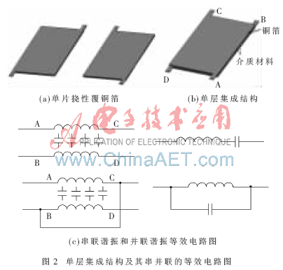
Figure 2 is a single-layer integrated structure and its series/parallel equivalent circuit diagram. The polyester film is cut into the shape shown in Figure 2(a), and two pieces are pressed and stacked. The upper and lower copper foils form an inductor, and the dielectric material in the middle forms a capacitor with the upper and lower copper foils, thus forming an integrated structure of inductance and capacitance, as shown in Figure 2(b). Such a structure can simultaneously obtain a certain inductance and capacitance, that is, after power is turned on, there is both magnetic field energy storage and electric field energy storage, and it is connected to the external circuit through an appropriate connection method, which can be equivalent to a series resonant or parallel resonant circuit. When the endpoints A and D are connected to the external circuit, the ends B and C are suspended, forming a series resonant form of inductance and capacitance; when the endpoints A and D are connected to the external circuit and the ends B and C are directly connected, a parallel resonant form of inductance and capacitance is formed, and its equivalent circuit is shown in Figure 2(c).
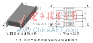
This paper proposes a planar integrated LC structure based on multi-layer flexible copper foil staggered parallel connection, which realizes the integration of series/parallel resonance. As in the manufacturing method of Figure 2, a total of 8 pieces of such shape are cut, stacked and pressed to realize the staggered parallel integrated LC unit structure. This structure can flexibly increase the capacitance, as shown in Figure 3(a), and its equivalent circuit is shown in Figure 3(b). The same LC unit structure with 4 terminals can be used to make multiple such integrated LC units. According to the multiple unit connection structure mentioned in reference [2], multiple units can be connected in series/parallel to achieve large inductance and large capacitance, large inductance and small capacitance, small inductance and large capacitance, and small inductance and small capacitance according to the needs of different inductance and capacitance values. The flexibility of integrated inductance and capacitance values is further increased.
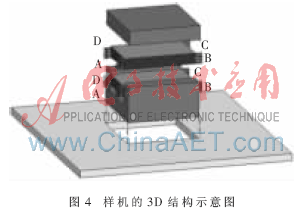
This paper first makes two four-layer staggered parallel integrated LC units. The CI type magnetic core is used to save the core column of the EI type magnetic core and increase the capacitance area. The circuit board corresponding to the CI type magnetic core is hollowed out, and then the four pins of each integrated LC unit are soldered to the circuit board. The leads between the two units can be routed from the circuit board. The magnetic core is buckled on the LC unit, which can not only save the space occupied by the overall passive components, but also increase the heat dissipation area of the magnetic core. If you want to increase the inductance value, when the integrated LC unit is powered on, the direction of the current of all integrated LC units should be in the same direction. For example, each integrated LC unit is input from the A and D terminals and output from the B and C terminals. The connection method can be realized on the circuit board; if you want to reduce the inductance value, you can make the current flow of several integrated LC units opposite, that is, input from the B and C terminals and output from the A and D terminals. The structural schematic diagram is shown in Figure 4.
1.2 Calculation of capacitance

It can be seen from equation (1) that if a larger capacitance C is needed, there are three ways to do this: (1) increase the relative dielectric constant r of the dielectric material; (2) increase the copper foil area w of the planar winding; (3) reduce the thickness d of the dielectric material.
If a larger capacitor is added, the advantage of using an interleaved parallel connection method [1] becomes apparent, as shown in Figure 2(b). If each unit is composed of n pieces of such structures stacked into the structure of Figure 3(a), the calculation formula for the capacitance C can be derived:

Similarly, when calculating the inductance, the inductance of an integrated LC unit is calculated first. According to reference [2], multiple units can be connected in different ways to obtain different inductance values as needed.
2 Simulation and Experiment
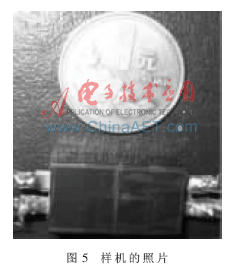
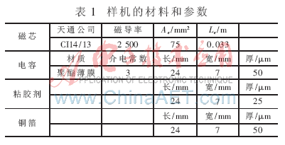
In this paper, a prototype of an integrated resonant LC unit based on staggered parallel flexible copper-clad foil material is made, as shown in Figure 5. The prototype uses CI14/13 magnetic core from Tiantong Company; the material of the integrated LC unit uses flexible copper-clad polyester film from Xianyang Zhongxin Electronic Materials Co., Ltd. The specific parameters are shown in Table 1.
The manufacturing method of the integrated LC unit is shown in Figure 3. The two four-layer integrated LC units are manufactured. The measured inductance value of each integrated LC unit is 3.6 μH and the capacitance value is 0.37 nF. According to the series connection of large inductors and large capacitors in reference [2], the inductance is calculated to be 14.3 μH and the capacitance is 0.83 nF. According to the parallel connection of large inductors and large capacitors, the inductance value is 57.1 μH and the capacitance is 0.21 nF. The parameters calculated for the prototype are shown in Table 2.
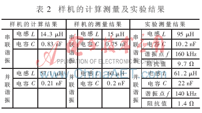
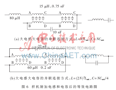
Due to the small dielectric constant and the small integrated capacitance value, the calculated resonant frequency of the integrated device is relatively large, reaching more than several MHz. The instrument used in the experiment is the 3255 automatic electronic parts analyzer of the Hua Instrument Co., Ltd., and the highest resonant frequency that can be measured is 200 kHz. Therefore, in actual measurement, it is necessary to add auxiliary inductors and capacitors to make their resonant frequency below 200 kHz. The additional inductors and capacitors are shown in Figure 6(a). The inductance value of the two units in the integrated LC in series structure is 15 μH, and the capacitance value is 0.75 nF. The calculated resonant frequency of the integrated device is 1.52 MHz. After adding 80 μH inductors and 10 nF capacitors in series in the integrated LC unit series structure, the resonant frequency of the integrated device is actually measured to be 160 kHz.
In the same experiment, the inductance value of the two units in the integrated LC parallel structure is 60 μH, the capacitance value is 0.2 nF, and the resonant frequency of the integrated device is calculated to be 1.45 MHz, as shown in Figure 6(b). After adding a 22 nF capacitor in parallel to the integrated LC unit parallel structure, the actual measured resonant frequency of the integrated device is 140 kHz. The values of the resonance points of the series resonance and parallel resonance with auxiliary inductance and capacitance measured by the actual instrument are shown in Table 2.
The PSPICE simulation of the added series integrated structure and parallel integrated structure is carried out. The simulation curve is shown in Figure 7. The series resonant frequency is 166.725 kHz and the parallel resonant frequency is 137.088 kHz. The results obtained are close to the actual measured results, proving that the prototype design is in line with the expected effect. If a relatively high dielectric constant is selected, such as Y5V, X7R and other materials, a capacitance value of several hundred nF or even above ? ? F level can be obtained, and no additional inductor and capacitor are required.

This paper proposes a new type of integrated LC structure, which is an integrated structure of multiple units based on multi-layer interlaced flexible copper foil, and can be placed in a CI-type magnetic core. A prototype was made and its parameters were experimentally verified. The experimental results show the effectiveness of this implementation method. This structure can be placed in the circuits of various resonant converters as the resonant part. If a CI-type magnetic core with high magnetic permeability or a large CI-type magnetic core is selected, the inductance value can be further increased, and if a relatively high dielectric constant is selected, the capacitance value can be further increased. These two improvements are more realistic for passive integration. By adjusting the number of layers and units, as well as the connection methods of different units, different inductance and capacitance values can be obtained, which is more flexible for the selection of passive components.
Previous article:Improving mobile phone antenna performance with new tuning technology
Next article:Analysis of factors in the transition from analog technology to IP surveillance
- High signal-to-noise ratio MEMS microphone drives artificial intelligence interaction
- Advantages of using a differential-to-single-ended RF amplifier in a transmit signal chain design
- ON Semiconductor CEO Appears at Munich Electronica Show and Launches Treo Platform
- ON Semiconductor Launches Industry-Leading Analog and Mixed-Signal Platform
- Analog Devices ADAQ7767-1 μModule DAQ Solution for Rapid Development of Precision Data Acquisition Systems Now Available at Mouser
- Domestic high-precision, high-speed ADC chips are on the rise
- Microcontrollers that combine Hi-Fi, intelligence and USB multi-channel features – ushering in a new era of digital audio
- Using capacitive PGA, Naxin Micro launches high-precision multi-channel 24/16-bit Δ-Σ ADC
- Fully Differential Amplifier Provides High Voltage, Low Noise Signals for Precision Data Acquisition Signal Chain
- Innolux's intelligent steer-by-wire solution makes cars smarter and safer
- 8051 MCU - Parity Check
- How to efficiently balance the sensitivity of tactile sensing interfaces
- What should I do if the servo motor shakes? What causes the servo motor to shake quickly?
- 【Brushless Motor】Analysis of three-phase BLDC motor and sharing of two popular development boards
- Midea Industrial Technology's subsidiaries Clou Electronics and Hekang New Energy jointly appeared at the Munich Battery Energy Storage Exhibition and Solar Energy Exhibition
- Guoxin Sichen | Application of ferroelectric memory PB85RS2MC in power battery management, with a capacity of 2M
- Analysis of common faults of frequency converter
- In a head-on competition with Qualcomm, what kind of cockpit products has Intel come up with?
- Dalian Rongke's all-vanadium liquid flow battery energy storage equipment industrialization project has entered the sprint stage before production
- Allegro MicroSystems Introduces Advanced Magnetic and Inductive Position Sensing Solutions at Electronica 2024
- Car key in the left hand, liveness detection radar in the right hand, UWB is imperative for cars!
- After a decade of rapid development, domestic CIS has entered the market
- Aegis Dagger Battery + Thor EM-i Super Hybrid, Geely New Energy has thrown out two "king bombs"
- A brief discussion on functional safety - fault, error, and failure
- In the smart car 2.0 cycle, these core industry chains are facing major opportunities!
- The United States and Japan are developing new batteries. CATL faces challenges? How should China's new energy battery industry respond?
- Murata launches high-precision 6-axis inertial sensor for automobiles
- Ford patents pre-charge alarm to help save costs and respond to emergencies
- New real-time microcontroller system from Texas Instruments enables smarter processing in automotive and industrial applications
- Showing goods + Qualcomm original QCA4020 development board
- CC2540 CC2541 low power consumption test and summary
- CRC (Cyclic Redundancy Check) Calculation Tool
- How to enable TI 15.4-Stack to support 470M frequency band
- EEWORLD University - SimpleLink Wi-Fi CC3120 Project Introduction
- How to communicate between ARM and DSP (non-multi-core SOC)
- OC5501-OC5502-LED automotive high and low beam solutions (no diode design, applied to automotive lights, MR16, architectural lighting)
- Share: About the working principle of fast charging
- Xiaomi 22.5W 10000 mAh fast charging power bank disassembly
- I would like to ask you guys, do I need to draw PCB in electronic competitions?

 Three-Phase 11 kW PFC + LLC Electric Vehicle On-Board Charging (OBC) Platform User Manual (ONSEMI Semiconductor)
 LLC resonant converter-Design Criteria and Device Selection
 開關電源專業英語


 京公网安备 11010802033920号