1 Overview
In industrial control applications, analog signal acquisition usually requires isolation technology to prevent power and ground line fluctuations caused by the start-up or switching of large electrical equipment from affecting weak current control systems. Common analog isolation methods include isolation amplifiers, electromagnetic isolation, and photoelectric isolation. Isolation amplifiers have good accuracy but high cost; electromagnetic isolation has large equipment size and poor accuracy.
Photoelectric isolation technology is a very effective anti-interference method. Optocouplers are common photoelectric isolation devices and are mainly used for digital quantity isolation transmission. If optocouplers are used to transmit analog quantities, the nonlinearity of the optocouplers must be very small to ensure the linearity of the input analog signal, which is difficult to achieve for most optocouplers. In order to achieve photoelectric isolation acquisition of analog quantities, analog/digital (A/D) conversion must be performed first before the converted digital quantity can be passed to the next level circuit via the optocoupler.
The traditional method is to directly use A/D chips for analog/digital conversion, and then transmit through optocouplers. According to the interface form, A/D chips can be divided into two types: parallel and serial access. The higher the acquisition accuracy of the parallel A/D chip, the more optocouplers are occupied by the parallel data line, and it is necessary to match the corresponding isolation signal to control the A/D conversion operation. This method has more wiring and occupies more resources; the serial A/D chip can save a lot of optocouplers, but it requires complex timing to complete the A/D read and write operations.
This paper proposes a method of using the micro single-chip microcomputer AT-tiny13 with integrated A/D for analog quantity isolation acquisition, and uses a single data line to complete data transmission. The analog quantity isolation acquisition adopts a simplified UART communication method, that is, a simplex communication method, which only requires a send line TXD and no receive line RXD. In this way, a single data line can undertake the task of sending A/D conversion values, and the receiver can easily obtain the isolated analog value as long as it has a hardware UART or software UART (receive).
2 ATtiny13 Introduction
ATtiny13 has 1 KB Flash, 64 bytes of EEPROM, 64 bytes of SRAM, 6 general-purpose I/O lines, 32 general-purpose working registers, an 8-bit timer/counter with compare mode, internal/external interrupts, and 4-channel 10-bit ADC.
3 Hardware Design
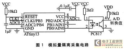
The analog isolation acquisition circuit is shown in Figure 1. ATtiny13 has two 10-bit ADCs that can be controlled and selected. Only one ADC is used in this design. Optocoupler PC817 is used to transmit A/D conversion values. CLKI represents the clock source introduced from the outside.

4 Software UART
ATtiny13 does not have an integrated UART function. To make up for this defect, the software can be used to control the I/O pins to simulate the UART function and output the A/D conversion value through optocoupler isolation according to the set acquisition rate.
4.1 Asynchronous Serial Protocol
When using UART asynchronous serial protocol communication, data is output bit by bit in sequence. The receiver determines the start and end of a frame of information by monitoring the start bit (low level is valid) and the stop bit (high level is valid). The data frame can also include several data bits and parity bits. The start bit and stop bit of the asynchronous serial protocol must be used, and the remaining bits can adjust the bit length. The format of the asynchronous serial protocol is as follows:

This article defines the frame format as: start bit (1 bit), data bit (5 bits), no parity bit, stop bit (1 bit). ATtiny13 has a built-in A/D converter with a precision of 10 bits, and the data bit is set to 5 bits wide, so it is necessary to send two asynchronous serial communication frames in succession to transmit a complete A/D conversion value. According to the high-bit first-out method, the high 5 bits of the A/D conversion value are sent first, and the low 5 bits are sent next.
4.2 Baud rate setting
Baud rate is a very important parameter in UART asynchronous serial communication. Both parties must communicate at an agreed rate to ensure successful communication. Baud rate is closely related to the time occupied by a "bit" in the asynchronous serial protocol. For binary signals, the time occupied by each bit in the data frame is the reciprocal of the baud rate. Therefore, how to accurately determine the time width of each bit becomes a key factor in ensuring the success of serial communication.
ATtiny13 does not have an integrated UART, but it has an 8-bit timer/counter inside, which can be controlled by software to generate baud rate. The MCU's built-in RC oscillator can be used as a clock source, but the oscillation frequency has a maximum error of ±10% and is greatly affected by temperature. This will cause an unstable baud rate, and data may not be received during communication, or data bits may be lost, garbled characters, and wrong codes may appear. ATtiny13 introduces a 7.372 8 MHz active crystal oscillator clock signal from the outside, thereby ensuring the stability of the main clock frequency.
The asynchronous communication baud rate can be calculated according to formula (1).
![]()
Where: XTAL is the main clock frequency introduced; Baud is the baud rate to be set; C is the timer clock division factor; n is the preloaded comparison value of the 8-bit timer/counter. The timer/counter works in CTC mode (clear the timer when compare match).
XTAL is 7.3728 MHz, Baud is set to 9600, and the timer clock signal is divided by 4 of the main clock (i.e. C=4), so n=192. Therefore, when the 8-bit timer/counter counts from 0 to 192, a comparison interrupt is generated, and the software controls the sending of a new bit of information.
4.3 Data transmission
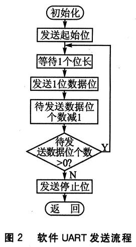
The UART asynchronous serial protocol stipulates that when there is no data frame to be sent, the logic "1" indicates that it is currently in an idle state. If there is data to be sent, first pull the transmit line TXD down to logic "0" and keep it for a basic time unit; then output it bit by bit in sequence according to the binary value of the data to be sent. The parity bit is not used in this design, and the related processing is omitted. After the 5-bit data is sent, TXD is immediately pulled up to logic "1" to indicate the end of the frame. The software UART sending process is shown in Figure 2.

The function Uart_SendByte(unsigned char data) implements the above function and sends 5 bits of data at a time. In the analog isolation acquisition, the microcontroller continuously obtains the A/D conversion value and sends it out by calling the above function.
Conclusion
This article introduces an analog isolation acquisition circuit based on ATtiny13. Due to the limitations of the maximum sampling rate of ADC and the transmission bandwidth of optocoupler PC817, it is only suitable for analog signals with slow frequency conversion. The circuit is small in size, low in cost, and simple in wiring. It has been used for finished switching power supply detection.
Previous article:Design of earthquake information acquisition module based on ADS1255
Next article:Improve the accuracy of analog-to-digital converters and reduce system costs
Recommended ReadingLatest update time:2024-11-16 21:28

- Popular Resources
- Popular amplifiers
- High signal-to-noise ratio MEMS microphone drives artificial intelligence interaction
- Advantages of using a differential-to-single-ended RF amplifier in a transmit signal chain design
- ON Semiconductor CEO Appears at Munich Electronica Show and Launches Treo Platform
- ON Semiconductor Launches Industry-Leading Analog and Mixed-Signal Platform
- Analog Devices ADAQ7767-1 μModule DAQ Solution for Rapid Development of Precision Data Acquisition Systems Now Available at Mouser
- Domestic high-precision, high-speed ADC chips are on the rise
- Microcontrollers that combine Hi-Fi, intelligence and USB multi-channel features – ushering in a new era of digital audio
- Using capacitive PGA, Naxin Micro launches high-precision multi-channel 24/16-bit Δ-Σ ADC
- Fully Differential Amplifier Provides High Voltage, Low Noise Signals for Precision Data Acquisition Signal Chain
- Innolux's intelligent steer-by-wire solution makes cars smarter and safer
- 8051 MCU - Parity Check
- How to efficiently balance the sensitivity of tactile sensing interfaces
- What should I do if the servo motor shakes? What causes the servo motor to shake quickly?
- 【Brushless Motor】Analysis of three-phase BLDC motor and sharing of two popular development boards
- Midea Industrial Technology's subsidiaries Clou Electronics and Hekang New Energy jointly appeared at the Munich Battery Energy Storage Exhibition and Solar Energy Exhibition
- Guoxin Sichen | Application of ferroelectric memory PB85RS2MC in power battery management, with a capacity of 2M
- Analysis of common faults of frequency converter
- In a head-on competition with Qualcomm, what kind of cockpit products has Intel come up with?
- Dalian Rongke's all-vanadium liquid flow battery energy storage equipment industrialization project has entered the sprint stage before production
- Allegro MicroSystems Introduces Advanced Magnetic and Inductive Position Sensing Solutions at Electronica 2024
- Car key in the left hand, liveness detection radar in the right hand, UWB is imperative for cars!
- After a decade of rapid development, domestic CIS has entered the market
- Aegis Dagger Battery + Thor EM-i Super Hybrid, Geely New Energy has thrown out two "king bombs"
- A brief discussion on functional safety - fault, error, and failure
- In the smart car 2.0 cycle, these core industry chains are facing major opportunities!
- The United States and Japan are developing new batteries. CATL faces challenges? How should China's new energy battery industry respond?
- Murata launches high-precision 6-axis inertial sensor for automobiles
- Ford patents pre-charge alarm to help save costs and respond to emergencies
- New real-time microcontroller system from Texas Instruments enables smarter processing in automotive and industrial applications
- Survey | We can help you overcome the difficulties in motor drive!
- A brief discussion on the role, advantages and disadvantages of portable display screens
- From Apple to Xiaomi, see the application of UWB technology in different fields
- Still about the problem of using DB9 connector for RS232 interface
- EEWORLD University Hall----Live Replay: TI Sitara? Multi-protocol Industrial Communication Optimization Solution, PLC Demo Real-time Demonstration
- [NXP Rapid IoT Review] + First Impressions and Use
- MSP430 serial write BOOTSTRAP and encryption fuse function
- Multisim Circuit System Design and Simulation Tutorial
- [NXP Rapid IoT Review] Reduce the CPU frequency (K64) to save power
- [GD32L233C-START Review] 13. CAU encryption algorithm DES/TDES

 Multi-port and shared memory architecture for high-performance ADAS SoCs
 CVPR 2023 Paper Summary: Transparency, Fairness, Accountability, Privacy, Ethics in Vision


 京公网安备 11010802033920号