Cut off the excitation current source
One technique used to reduce errors due to mismatched excitation currents is to alternate the current flow path between the two inputs. This is often referred to as “chopping.” Excitation currents are injected into the RTD circuit and then swapped while taking readings at each setting. The average of the two readings will not be affected by the mismatch between the two excitation currents. In most integrated solutions, this is accomplished by alternating the excitation current flow path to the two outputs using a built-in multiplexer. Figure 1 shows how the excitation current is chopped in this circuit.
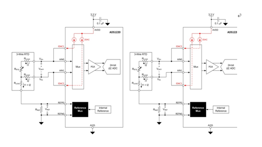
Figure 1: Cutting off the excitation current
When the excitation current is swapped, the system designer must wait until the input signal settles in order to make a valid measurement. The settling time is based on the selected analog-to-digital converter (ADC) and any external filters that have been enabled. Switching the multiplexer and waiting to get a reading adds latency to the measurement system, which may be undesirable in some applications. As the timing becomes more complex, the digital processing algorithms required to convert the average result into a temperature reading become more cumbersome.
Three-wire RTD measurement system with high-side reference
A more effective alternative to cutting off the excitation current is to place the reference resistor on the high side of the RTD sensor (Figure 2). In this configuration, only one excitation current flows through both the reference resistor and the RTD. The second excitation current is used only for three-wire RTD lead resistance cancellation. Because only one excitation current generates the reference and input voltages, current source mismatch and mismatch drift will no longer affect the ADC transfer function. Any mismatch error can only affect the effectiveness of the RTD lead cancellation, which is no different from the original circuit.
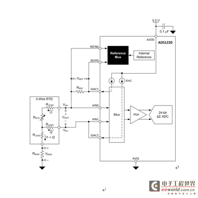
Figure 2: High-side reference resistor configuration
High-side reference circuit configuration
By moving the low-side reference resistor to the high side of the RTD, the new configuration introduces some additional design challenges. First, an additional resistor, RBIAS, must be connected from the RTD to ground. The voltage VBIAS across RBIAS will shift the RTD voltage within the linear input common-mode voltage range of the ADC. This must be achieved while keeping the voltage at the output of the current output digital-to-analog converter (IDAC) below its compliance voltage rating.
Equation (1) explains the input common-mode voltage VCM applicable to the circuit in Figure 2.

The input common-mode voltage for programmable gain amplifiers (PGAs) must be kept within the range outlined in the product data sheet. Equation (2) shows two limits for the minimum common-mode voltage, VCM MIN. Use the larger of these two values for VCM MIN. Equation (3) explains the maximum common-mode voltage, VCM MAX.

The voltage at the output of the IDACs must not exceed the compliance voltage, otherwise they will not function properly. Equation (4) explains the compliance voltage of the IDACs.

In this circuit configuration, the maximum IDAC output voltage is at IDAC1, denoted by VIDAC1 MAX. This voltage at VIDAC1 can be calculated using equation (5).

Table 1 shows the minimum and maximum common-mode voltage and IDAC compliance voltage values based on a 3.3V supply.
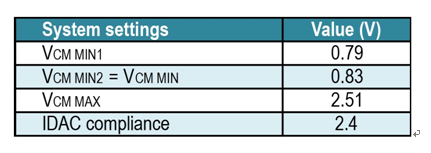
Table 1: Common-mode and IDAC compliance voltage limits when using a +3.3V supply

In a high-side reference configuration, the voltage at the IDAC output is increased because RBIAS is added - this reduces the available headroom. To meet the IDAC voltage compliance requirements, it may be necessary to reduce the reference or bias voltage by adjusting the IDAC current or resistor value. In turn, different IDAC currents may require adjustments to the PGA gain to maintain system resolution.
With the proposed high-side reference solution, it is still feasible to meet the input common mode and IDAC compliance voltage limits. First, select a bias voltage that exceeds VCM MIN. This maximizes the margin to meet the IDAC compliance voltage requirement. Then, select the reference voltage and PGA gain setting based on the maximum RTD voltage to maximize the system resolution.
Table 2 lists the circuit values for a properly optimized high-side reference circuit using a +3.3V supply. The VCM MIN and VCM MAX voltages and the VIDAC1 MAX voltage for this circuit are also listed. Note that the maximum ADC input voltage fully utilizes most of the VREF voltage range while ensuring that the common-mode and IDAC compliance voltage limits listed in Table 1 are not violated.
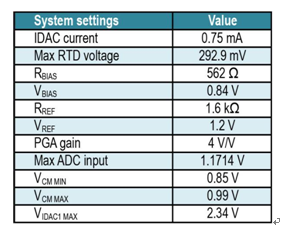
Table 2: Circuit parameters for high-side reference circuit
High-side reference circuit total error
We analyze the errors contributed by the ADC and RREF. While the equations and error sources remain the same, the input referred voltage error will change based on the newly selected IDAC current and component values in the circuit. Table 3 summarizes the error sources and calculates the total probable error for the high-side reference circuit at 25°C. As shown, the error from the IDAC mismatch can be eliminated. The total error can be calculated using equation (6).


Table 3: Total error (TA = 25°C).
The total input referred voltage error can again be converted to a temperature error.

Eliminating the excitation current mismatch error reduces the uncalibrated temperature error by 67% – the calculated temperature error in the original low-side reference configuration is 1.589°C.
High-side reference circuit drift error
Table 4 lists the temperature drift error of the ADS1220 over the system operating temperature range (TA = -40°C to +85°C). As shown, using a high-side reference configuration also eliminates the error caused by IDAC mismatch drift.
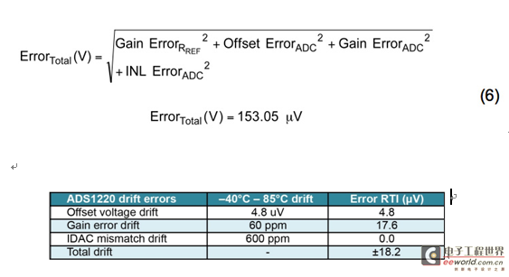
Table 4: Temperature drift error over the system operating temperature range (-40°C to +85°C)
Eliminating the error due to IDAC mismatch significantly reduces the input referred drift error (from 119.6μV to only 18.2μV). The total drift error now only adds ±0.062°C of temperature error over the -40°C to 85°C temperature range, compared to ±0.306°C of temperature error in the low-side reference circuit. Eliminating the error from excitation current mismatch reduces the need or requirement for over-temperature calibration.
Summarize
In standard ratiometric three-wire RTD measurement circuits, excitation current mismatch is often the largest source of error, both at room temperature and over the operating temperature range. Cutting off the excitation current is a simple method to reduce the effects of excitation current mismatch in traditional low-side reference ratiometric RTD acquisition circuits. Changing the circuit to a high-side reference configuration eliminates the effects of excitation current mismatch and current mismatch drift while achieving zero measurement latency and minimizing additional component count. The high-side configuration can also be used for low supply voltages as long as the input common-mode voltage and excitation current compliance voltage limits are met.
This article highlights two solutions that can reduce or eliminate the errors caused by IDAC mismatch. It shows how to reconfigure the circuit as a high-side reference circuit so that the effects of excitation current mismatch and mismatch drift can be completely eliminated with only one additional component.
references
1. Download the ADS1200 product manual.
2. Check out the TI E2E Community's Precision Hub blog, where you can search for related topics, including this one.
Previous article:ADC Clock Input Considerations
Next article:Effects of Excitation Current Mismatch in a Three-Wire RTD Measurement System
- High signal-to-noise ratio MEMS microphone drives artificial intelligence interaction
- Advantages of using a differential-to-single-ended RF amplifier in a transmit signal chain design
- ON Semiconductor CEO Appears at Munich Electronica Show and Launches Treo Platform
- ON Semiconductor Launches Industry-Leading Analog and Mixed-Signal Platform
- Analog Devices ADAQ7767-1 μModule DAQ Solution for Rapid Development of Precision Data Acquisition Systems Now Available at Mouser
- Domestic high-precision, high-speed ADC chips are on the rise
- Microcontrollers that combine Hi-Fi, intelligence and USB multi-channel features – ushering in a new era of digital audio
- Using capacitive PGA, Naxin Micro launches high-precision multi-channel 24/16-bit Δ-Σ ADC
- Fully Differential Amplifier Provides High Voltage, Low Noise Signals for Precision Data Acquisition Signal Chain
- Innolux's intelligent steer-by-wire solution makes cars smarter and safer
- 8051 MCU - Parity Check
- How to efficiently balance the sensitivity of tactile sensing interfaces
- What should I do if the servo motor shakes? What causes the servo motor to shake quickly?
- 【Brushless Motor】Analysis of three-phase BLDC motor and sharing of two popular development boards
- Midea Industrial Technology's subsidiaries Clou Electronics and Hekang New Energy jointly appeared at the Munich Battery Energy Storage Exhibition and Solar Energy Exhibition
- Guoxin Sichen | Application of ferroelectric memory PB85RS2MC in power battery management, with a capacity of 2M
- Analysis of common faults of frequency converter
- In a head-on competition with Qualcomm, what kind of cockpit products has Intel come up with?
- Dalian Rongke's all-vanadium liquid flow battery energy storage equipment industrialization project has entered the sprint stage before production
- Allegro MicroSystems Introduces Advanced Magnetic and Inductive Position Sensing Solutions at Electronica 2024
- Car key in the left hand, liveness detection radar in the right hand, UWB is imperative for cars!
- After a decade of rapid development, domestic CIS has entered the market
- Aegis Dagger Battery + Thor EM-i Super Hybrid, Geely New Energy has thrown out two "king bombs"
- A brief discussion on functional safety - fault, error, and failure
- In the smart car 2.0 cycle, these core industry chains are facing major opportunities!
- The United States and Japan are developing new batteries. CATL faces challenges? How should China's new energy battery industry respond?
- Murata launches high-precision 6-axis inertial sensor for automobiles
- Ford patents pre-charge alarm to help save costs and respond to emergencies
- New real-time microcontroller system from Texas Instruments enables smarter processing in automotive and industrial applications
- Pingtouge RVB2601 board-IIC bus test
- 【GD32E503 Review】 + littlegl ported to GD32E503V-EVAL
- EEWORLD University ---- Deep Learning Course (NYU, Spring 2020) Yann Lecun
- VICOR invites you to participate in the High Performance Power Conversion Seminar (venues: Beijing, Shenzhen, Shanghai, etc.)
- [TI recommended course] #Engineer It series course #Lesson 1 Loop bandwidth in phase-locked loop applications
- EEWORLD University ---- RS-485 Overview
- How to set up the serial port of 51 microcontroller to communicate with PC
- Step-by-step considerations for designing wide-bandwidth, multichannel systems
- DSP Digital Image Design Report
- Digital Integrated Circuits—Circuits, Systems, and Design (Second Edition)

 Offline AC-DC Power Supply Design Guide Using BCDPWM Controller AP3103
 That s how the temperature monitor/controller came to be.It was an obvious task for a small proces


 京公网安备 11010802033920号